“CIAO M”
2023 Custom Line 106' for Sale
$11,490,000
Miami, FL, US

$11,490,000
Miami, FL, US

Watch a video of this 106' Custom Line 106' Yacht. Priced at $11,490,000 Currently in Miami, FL, US
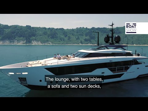

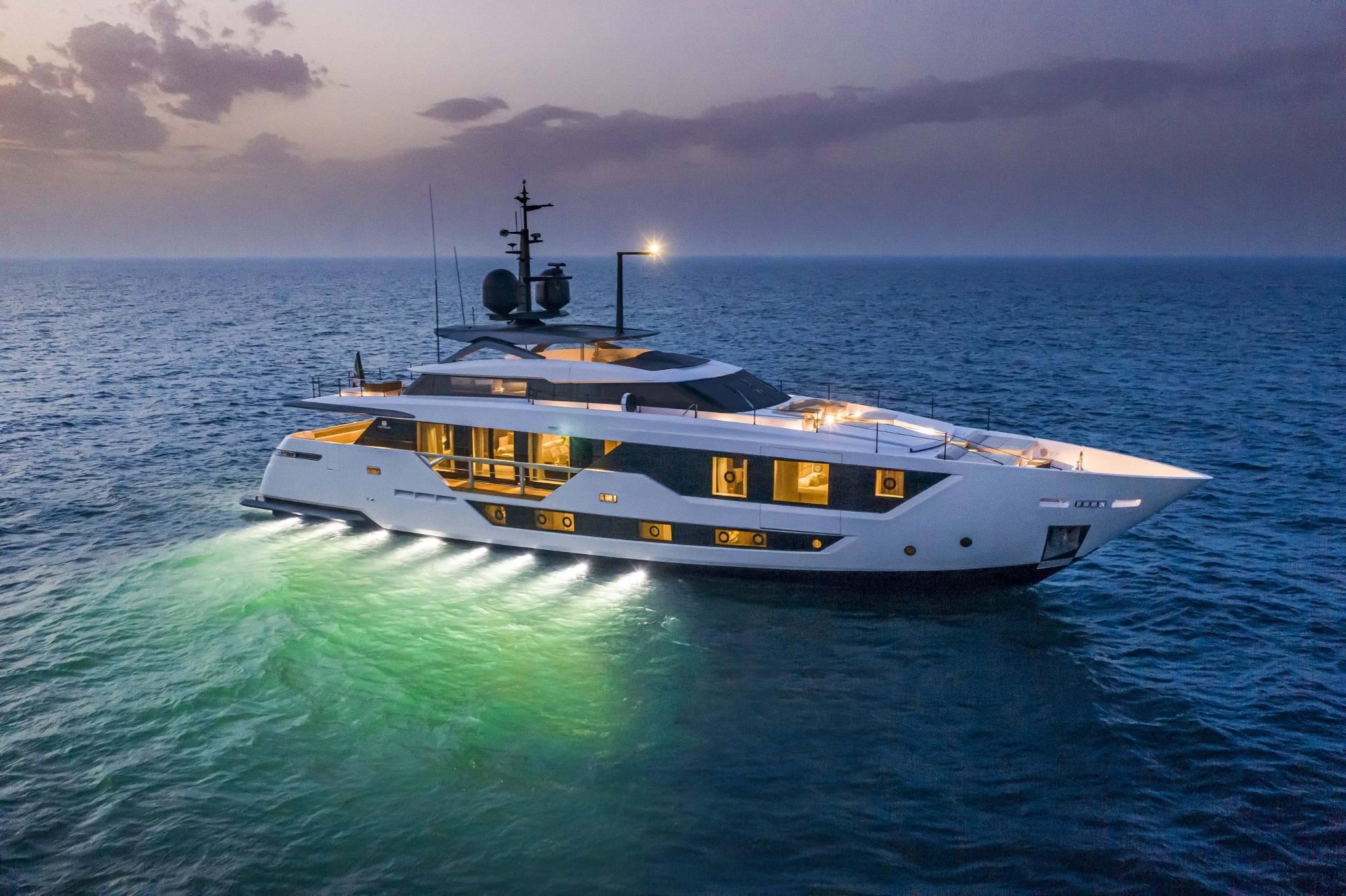
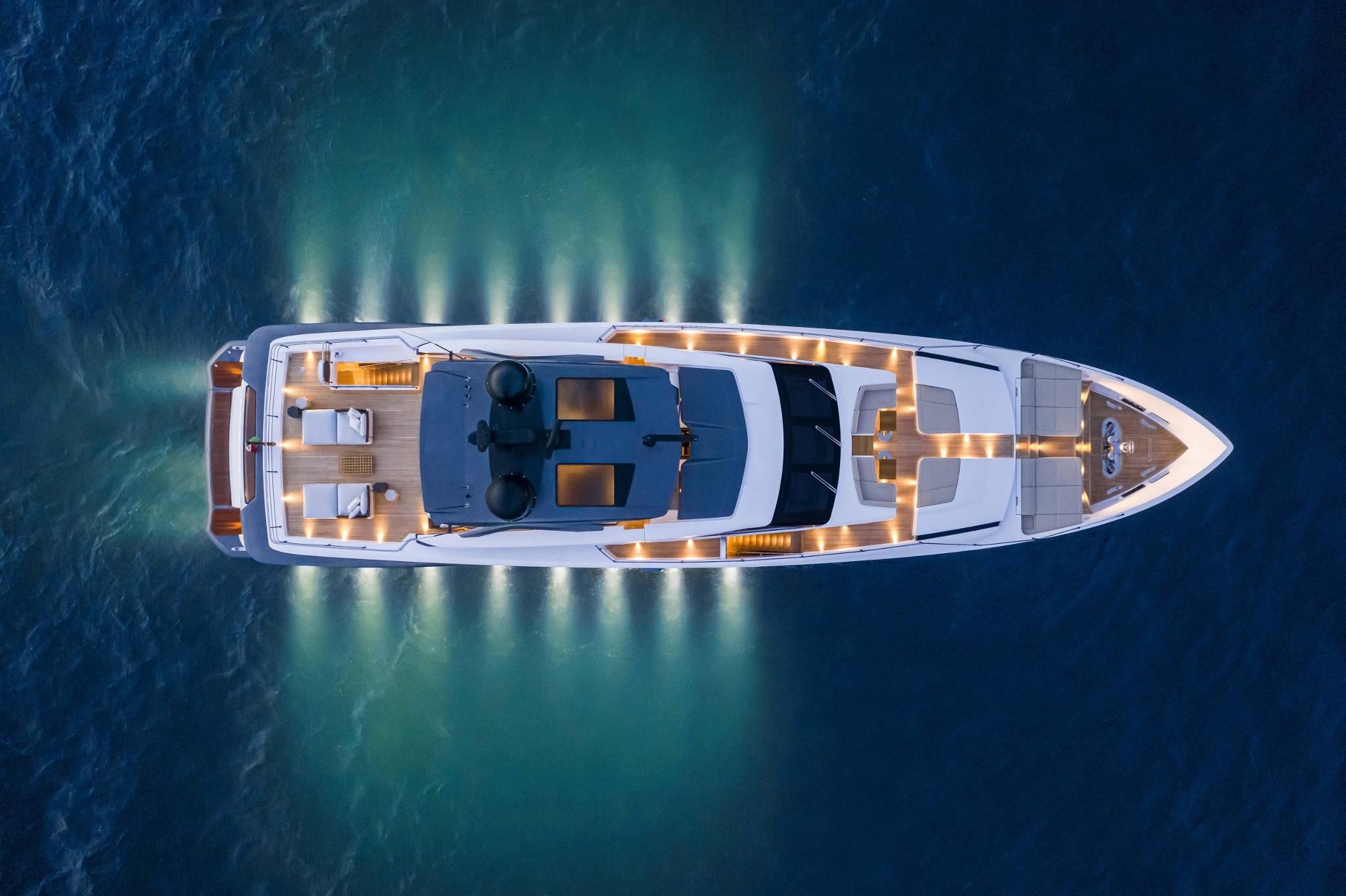
2023 Custom Line 106' | CIAO M
Perfect condition - Has never been used!
Only 80 Hours!
Full Warranty Available!
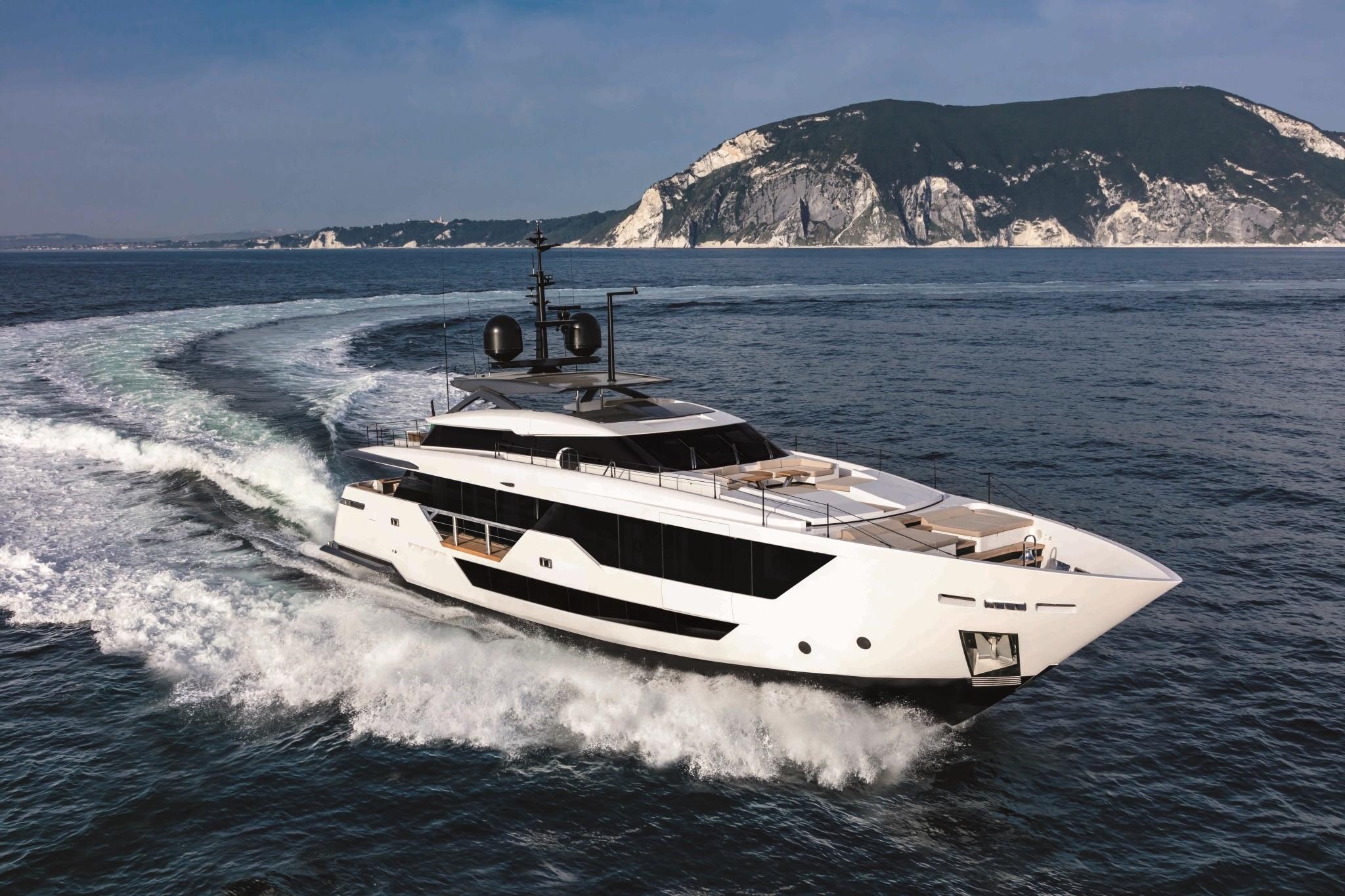
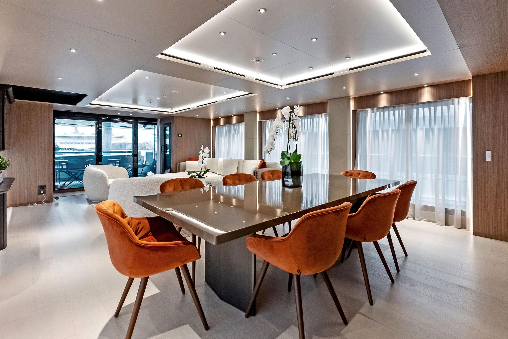
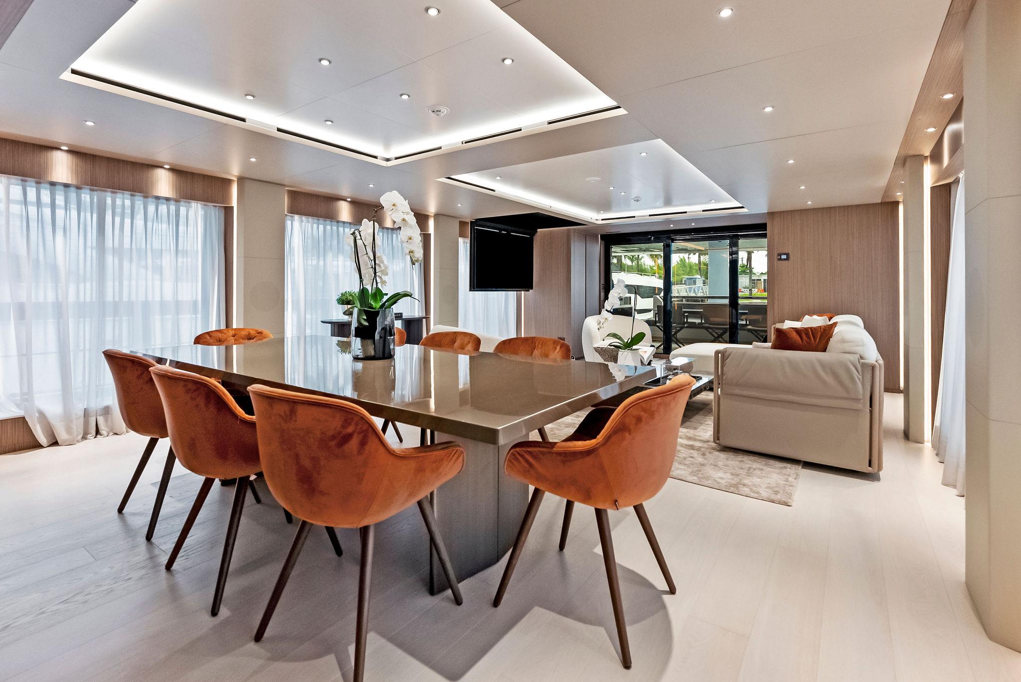
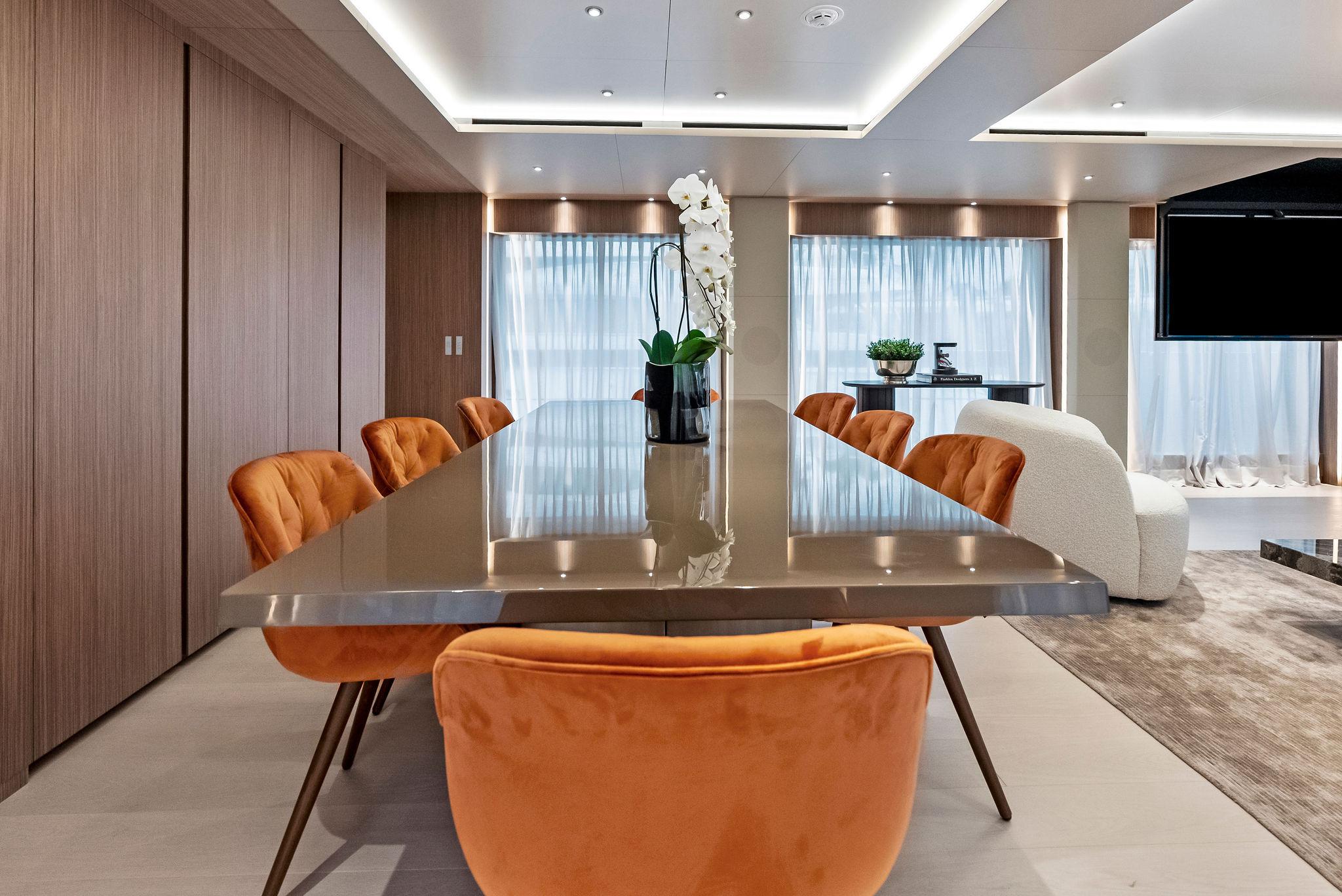
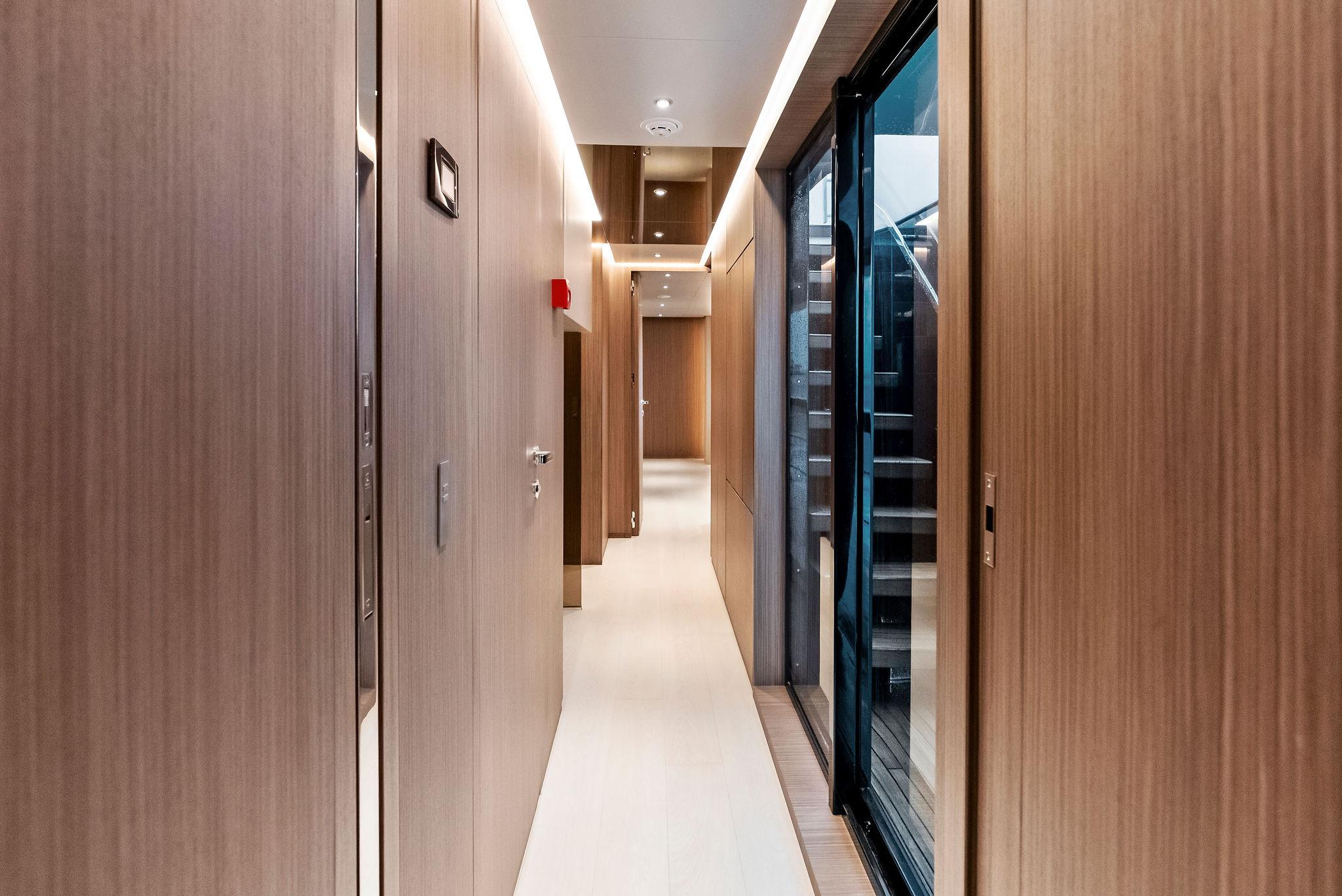
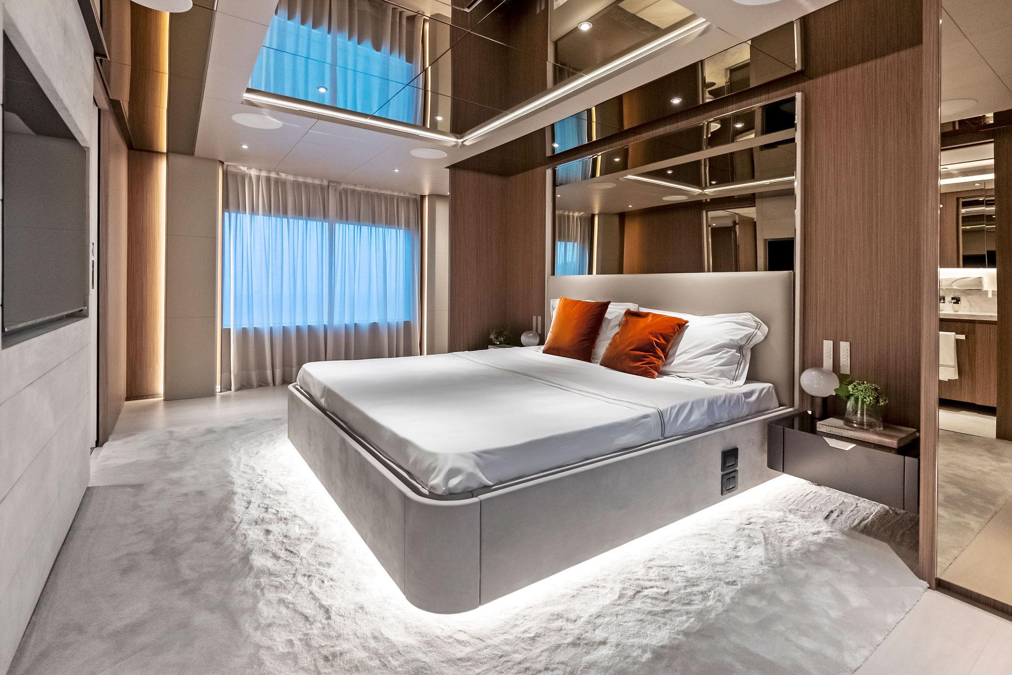
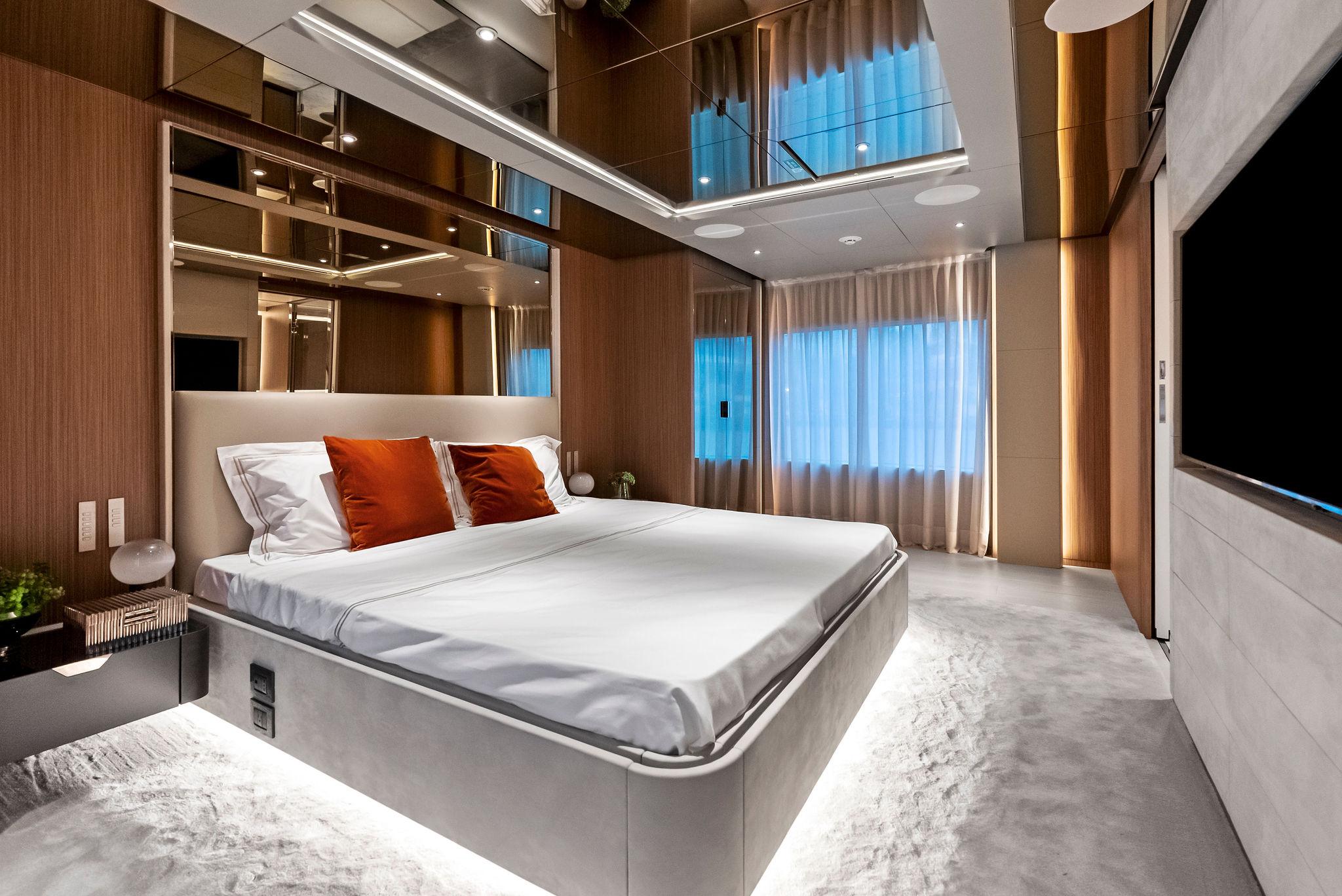
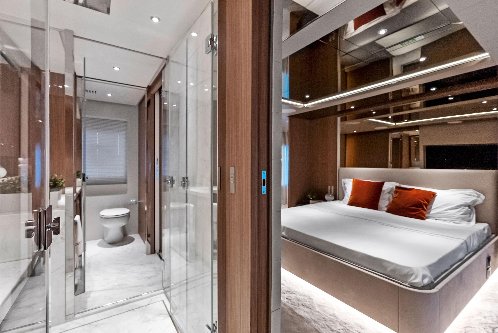
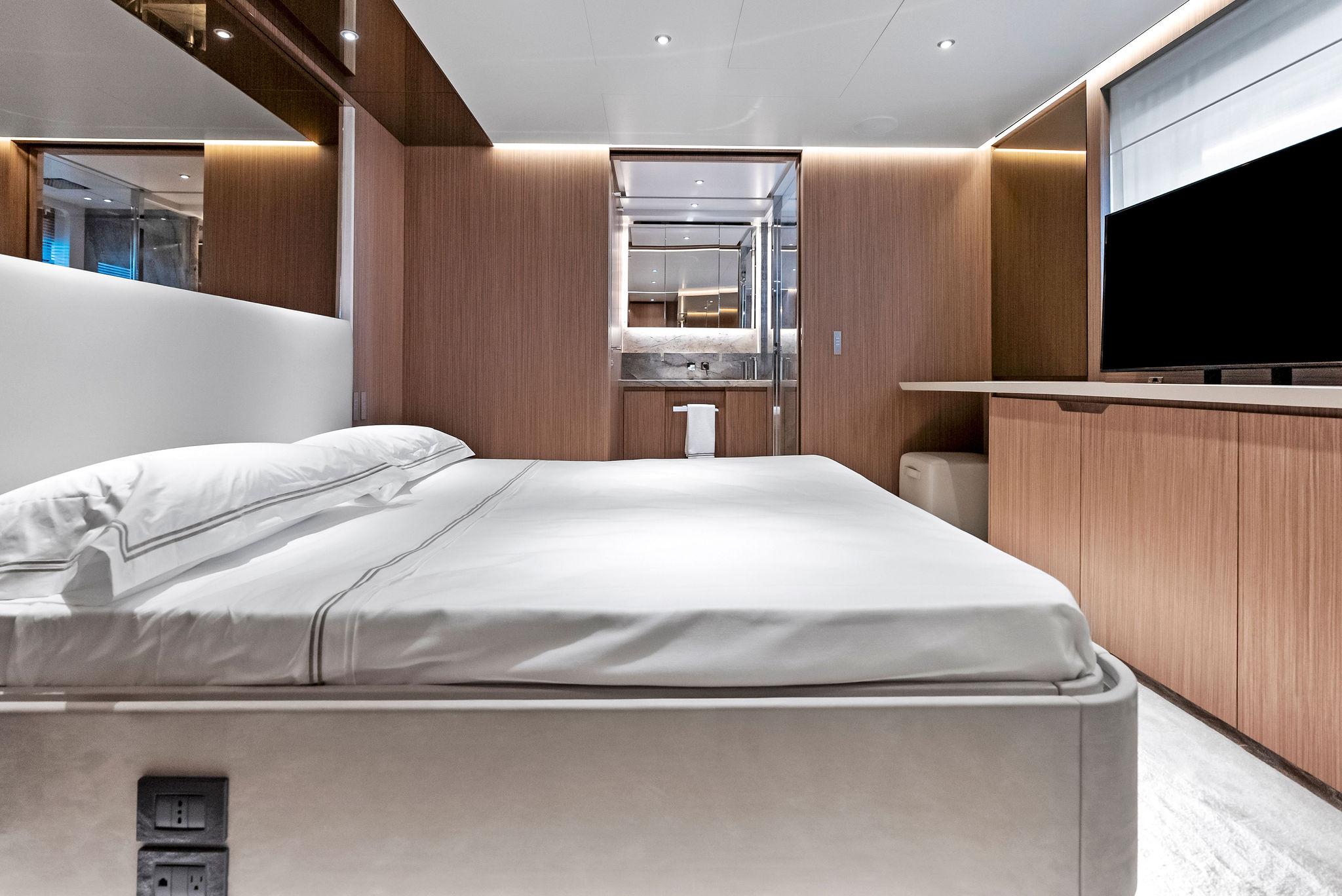
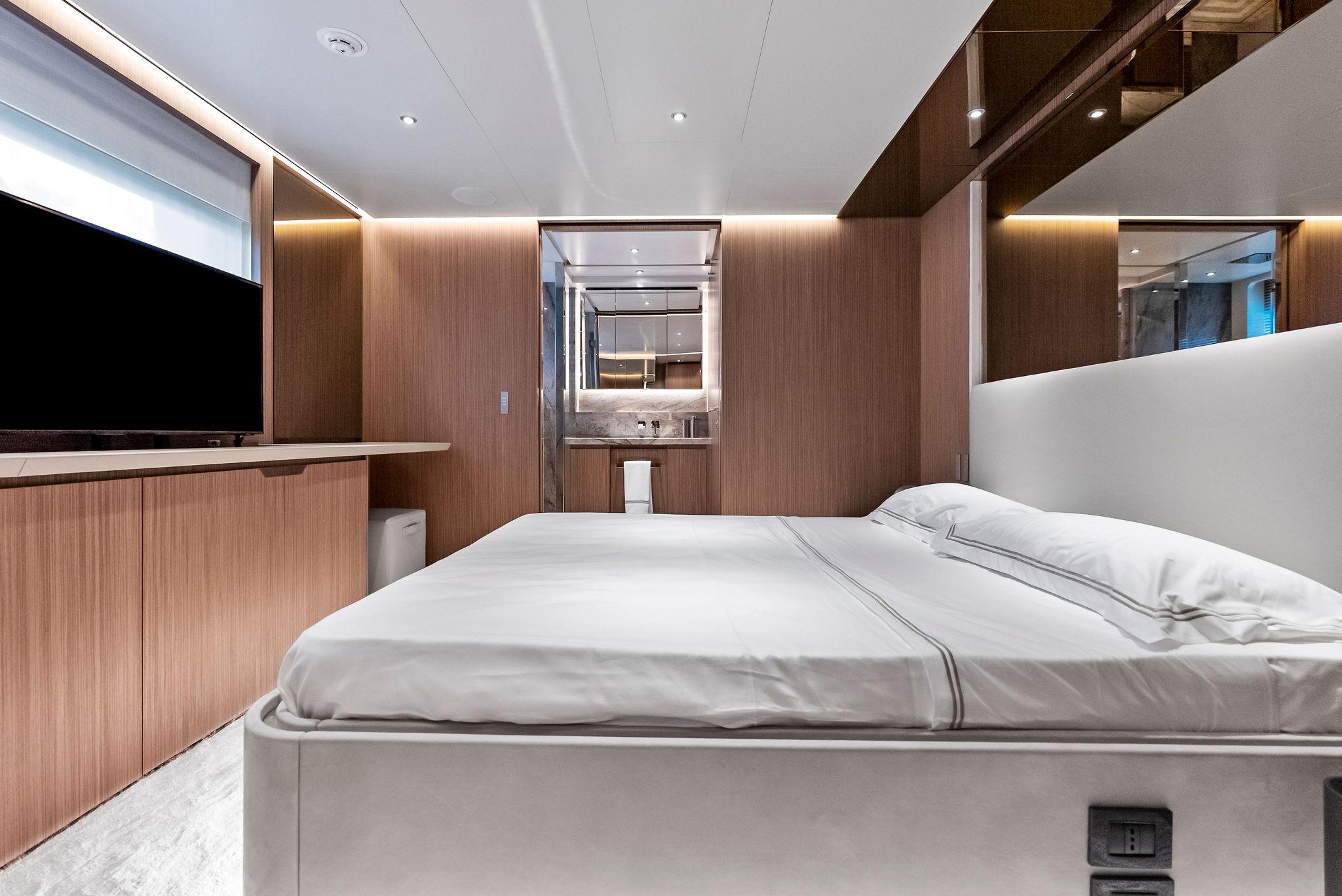
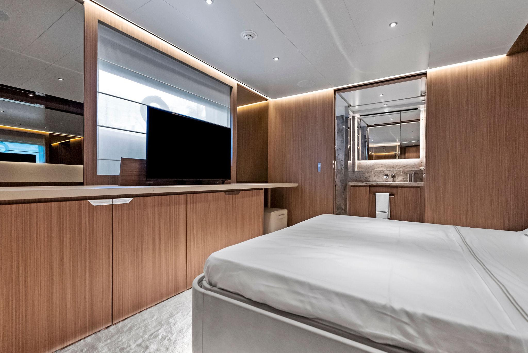
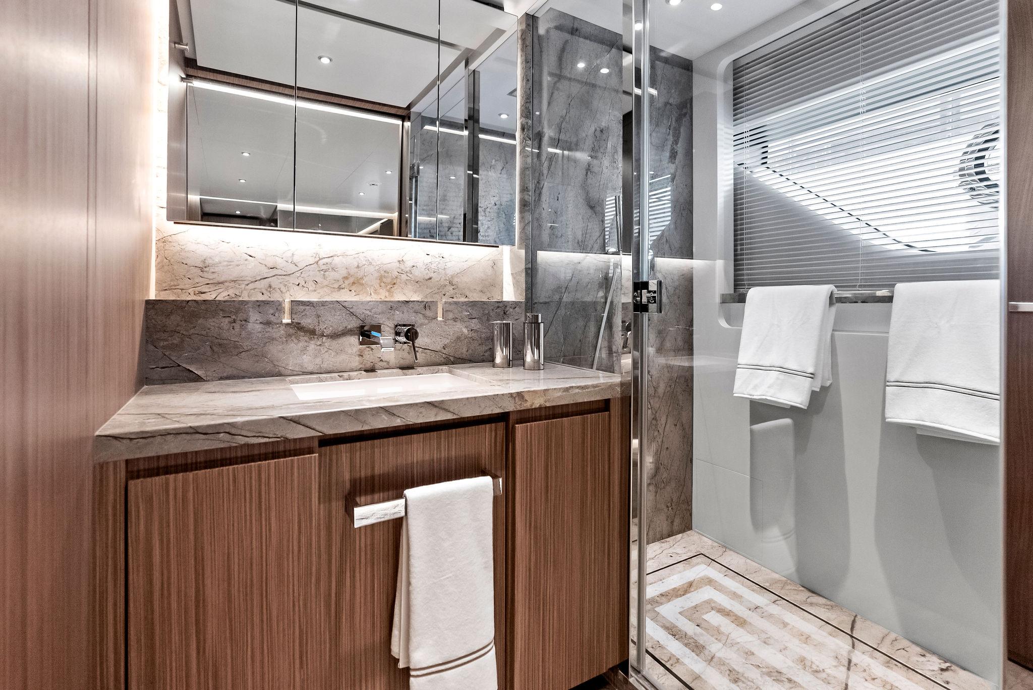
This stunning 2023 Custom Line 106 is a masterpiece of Italian design and engineering. With only 80 engine hours and never having been used, this yacht is in pristine, like-new condition. It offers unparalleled luxury, cutting-edge technology, and exceptional performance, making it the ultimate choice for discerning yacht owners.
Located in Miami, FL, this vessel is ready for immediate delivery. The full warranty ensures peace of mind, covering all aspects of this magnificent yacht.
Key Features
This is an extraordinary opportunity to own an almost brand-new Custom Line 106 without the wait. This yacht is a rare find and won’t be on the market for long.

| Name | CIAO M |
| Price | $11,490,000 |
| Year | 2023 |
| Length Overall | 106 ft |
| Draft | 6.67 ft |
| Beam | 24.25 ft |
| Location | Miami, FL, US |
| Hull Material | Fiberglass |
| Location | Port |
| Power | 2000 HP |
| Fuel | diesel |
| Hours | 80 |
| Make | MTU |
| Model | M96L 16V |
| Type | Inboard |
| Location | Starboard |
| Power | 2000 HP |
| Fuel | diesel |
| Hours | 80 |
| Make | MTU |
| Model | M96L 16V |
| Type | Inboard |
Hull and Structure
HULL GENERAL
Hull form is designed on the basis of experience on previous similar Yachts, taking into account resistance, seakeeping and maneuverability characteristics.
The structural design and assessment is designated according to the most recent experience acquired by the Builder in design and construction of GRP for this type of Yacht and according to the RINA Classification Rules. The hull is divided into 3 watertight compartments, by the watertight collision bulkhead on the forepeak and watertight Engine room bulkhead, in accordance with Classification rules. The watertight collision bulkhead is positioned in accordance with the Classification Rules. A chain locker space suitable to contain both port and starboard chain cables are provided forward the watertight collision bulkhead.
HULL & DECK MATERIALS AND CONSTRUCTION
The Yacht has been constructed with a combination of sandwich and single skin GRP laminate using mat, unidirectional/biaxial E-glass/carbon fibers and closed-cell foam cores for sandwich, according to the structural drawings approved by the Classification Rules. A skin coat is made using vinylester resin to prevent osmosis of the inner laminate. Hull (both bottom and sides) and deck is made (mainly) of sandwich laminate by infusion process.
The hull structure is framed with main longitudinal structural members and transversal bulkheads, and secondary transversal structural members.
Fuel oil and black, grey, fresh water tanks will be integrated. Each tank have at least one manhole. Internal tank surfaces will be treated using vinylester resin as follows:
• Fuel tanks: 2 C-glass layers• Fresh water: food grade gelcoat• Other tanks: 2 additional E-glass layers
The deck structure is made of longitudinal/transversal structural members and sup- ported by bulkheads.
Bulkheads are made of GRP sandwich and composite marine plywood. GRP bulwark is integrated into the hull sides.
The bulwark is equipped with fairleads, access doors and freeing ports, in com- pliance with the Classification Rules. A GRP bow thruster tunnel has been installed on the hull by proper lamination as well as watertight connections through watertight bulkheads.
STRUCTURAL REINFORCEMENT, PLATES AND INSERTS
Brass or equivalent inserts are fitted to distribute concentrated stress due to the fastening of heavy machinery and parts to the hull structure (eg. hand rails, pillars,…). Hawse piping is made by GRP laminate. Installations are in compliance with the Classification Rules, where applicable.
HULL SHELL DOORS
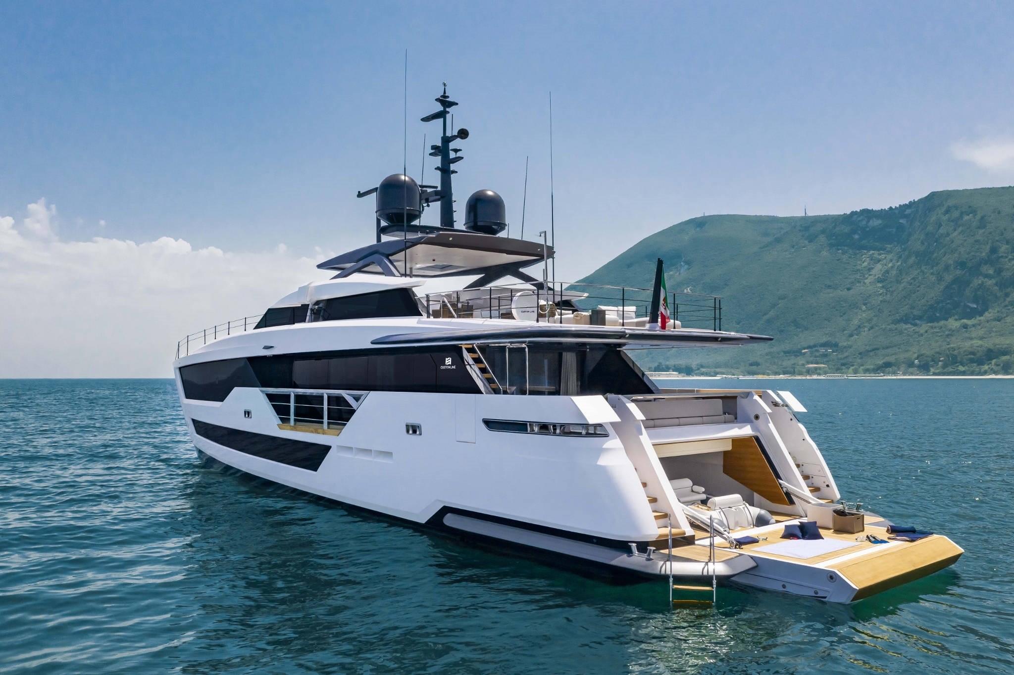
The Yacht is equipped with the DMT (Dual Mode Transom) system, a patent by Ferretti Group. The transom door is able to open in two alternative modes:
Both the movements are associated with the lowering of the central portion of the aft platform.
The whole kinematics is electro/hydraulically operated.
On the forward garage an hinged shell door are installed opening upward and electrohydraulically actuated.
The design and installation is in compliance with the Classification Rules.
MACHINERY AND EQUIPMENT FOUNDATIONS
Marine plywood, epoxy fiberglass sheets (GPO3), brass and steel inserts, integrated to the Builder discretion, are provided as machinery and equipment supports.
Aluminum structural frames dedicated to the gensets are installed.
The engine room and control room floor are made in knurled aluminum and sup- ported by aluminum profiles frame.
SUPERSTRUCTURE MATERIALS AND CONSTRUCTION
The superstructure are constructed with a combination of sandwich and single skin GRP laminate by infusion process using mat, unidirectional/biaxial E-glass/carbon fibers and closed-cell foam cores for sandwich according to the structural drawings approved by the Classification Rules. The structural frame is made of main longitudinal and secondary transversal structural members, using carbon fibers on specific areas.
HARD TOP
The hardtop and lateral supports are made composite structure and supported also by pillars at forward and aft ends. The hardtop includes:
PAINTING AND FINISHING
All the products used for the painting ARE standard finishing suitable for this type of Yacht. The Yacht has been delivered with a premium quality, industry recognized marine coating.
EXTERNAL FINISHING
The quality of polished gelcoat parts finishing is defined by builder quality standards and control procedures. The finishing is white gelcoat except beauty line and other parts.
The yacht external surfaces are finished according the different zones; each zone is characterized by its own quality levels and checks. In general the acceptance criteria involves fairness, cracks, gloss, orange peel. Antiskid areas are in accordance with the related plan, and and antifouling paint is applied to the underwater portion of the hull.
AFT AND FORWARD GARAGES
Aft garage has gelcoat finish except for the ceiling where wood has been installed. Forward garage walls and ceilings have gelcoat finish.
BOW THRUSTER SPACE
The bow thruster space is closed by a bolted metallic panel.
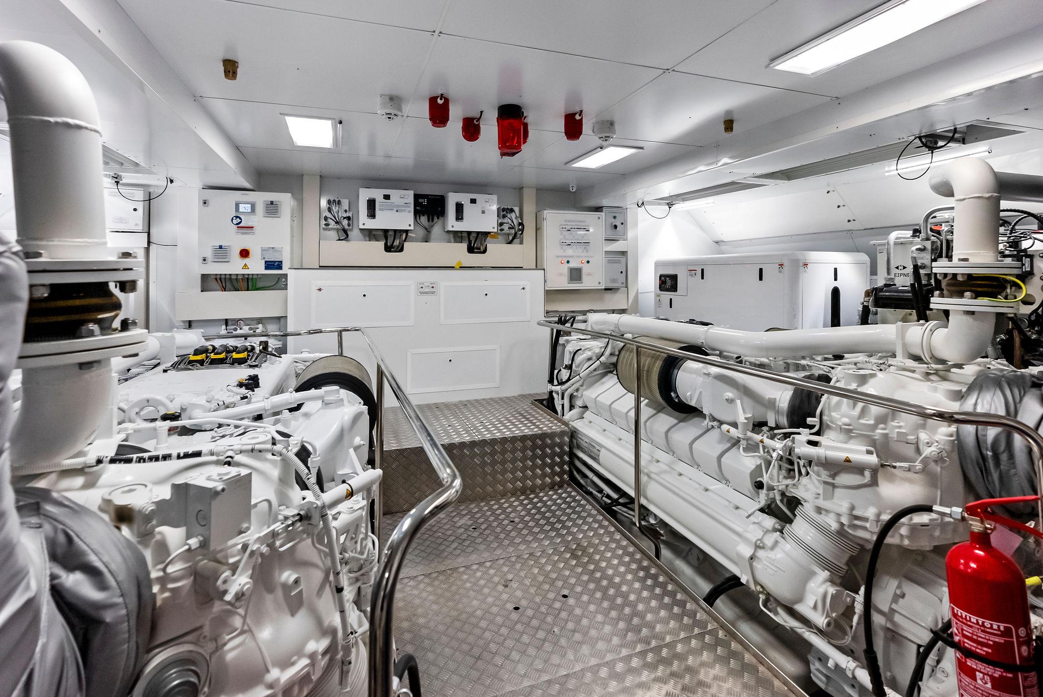
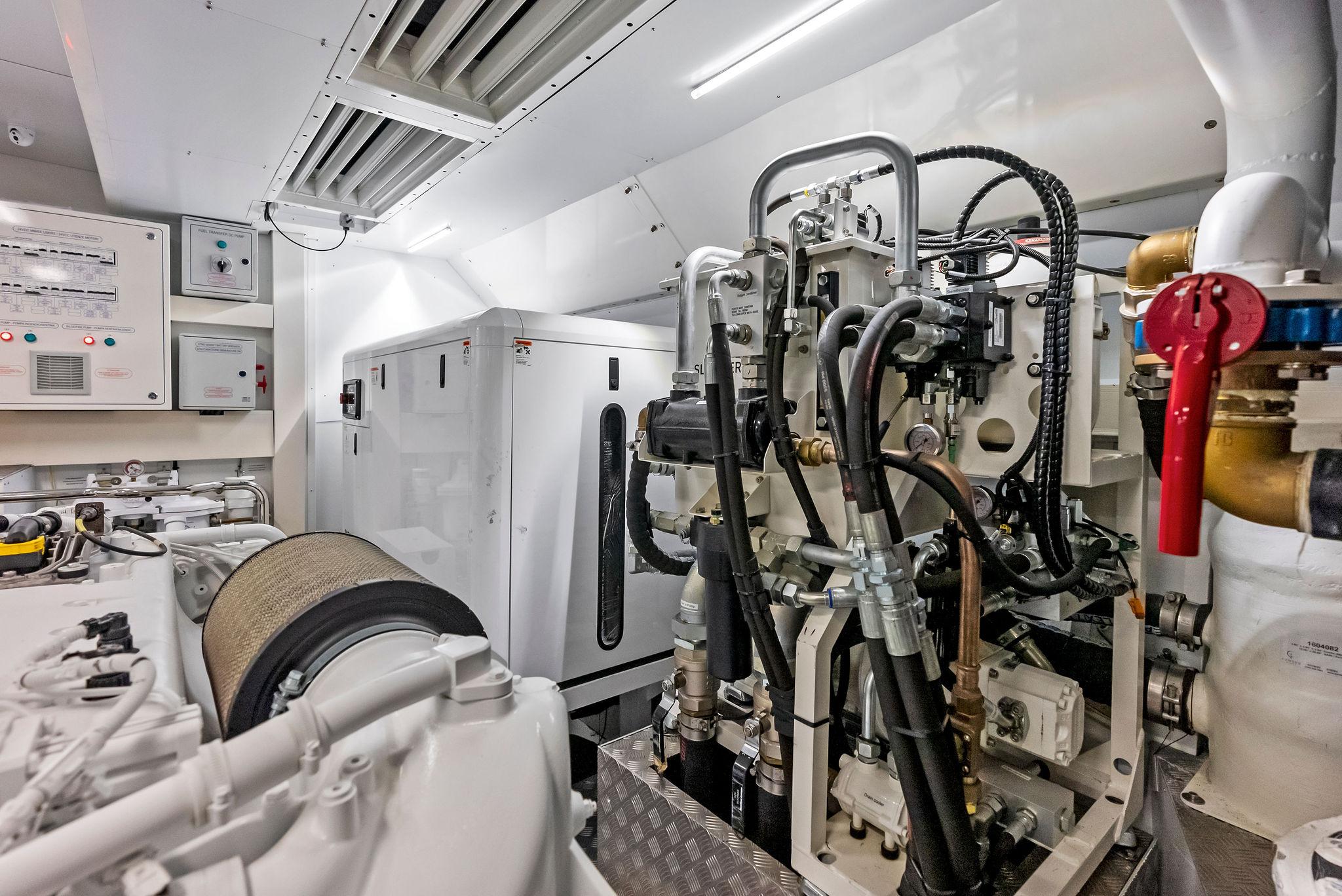
ENGINE ROOM
The engine room walls are covered with aluminum/rubber sandwich plate and ceiling with Di Bond or similar metal sheeting. The paneling is smooth white finish easy to clean and presents a hard abrasion resistant surface inside the machinery spaces.
AISI 304 handrails are fitted around the engines and along stairways or where deemed necessary for safety reasons. Handrails is dismountable.
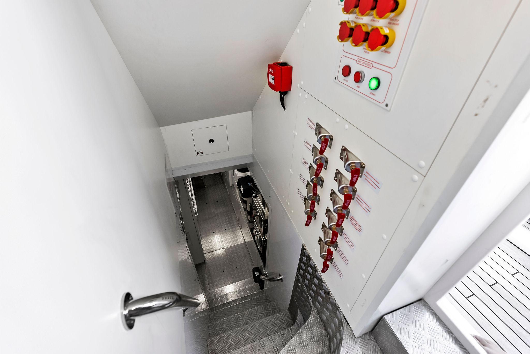
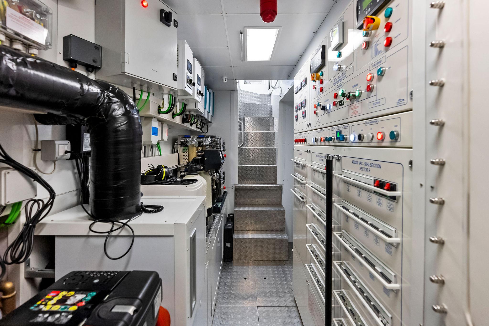
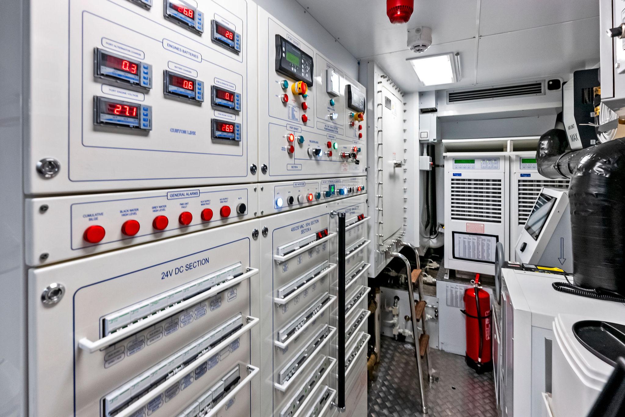
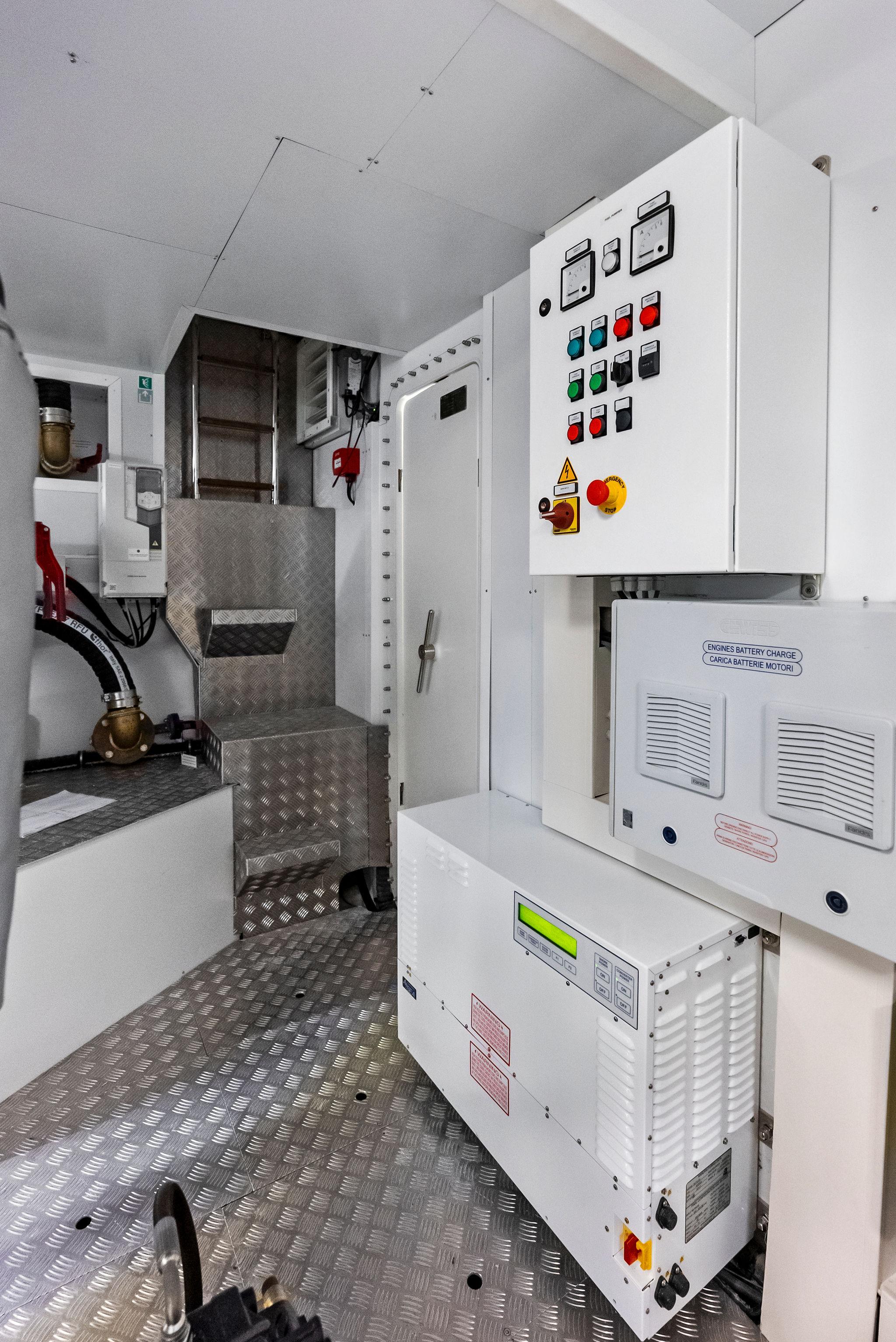
ENGINE CONTROL ROOM
The control room is located aft of the engine room. A watertight hinged door gives access to the engine room. The flooring is aluminum plate. The room is well lit, and fitted with air conditioning.
CATHODIC PROTECTION
HULL GRIDS
Main Machinery
TRANSMISSIONS
The main engine is directly coupled with the gearbox;. the propulsion assembly (main engine and gear box) is elastically supported on resilient mounts.
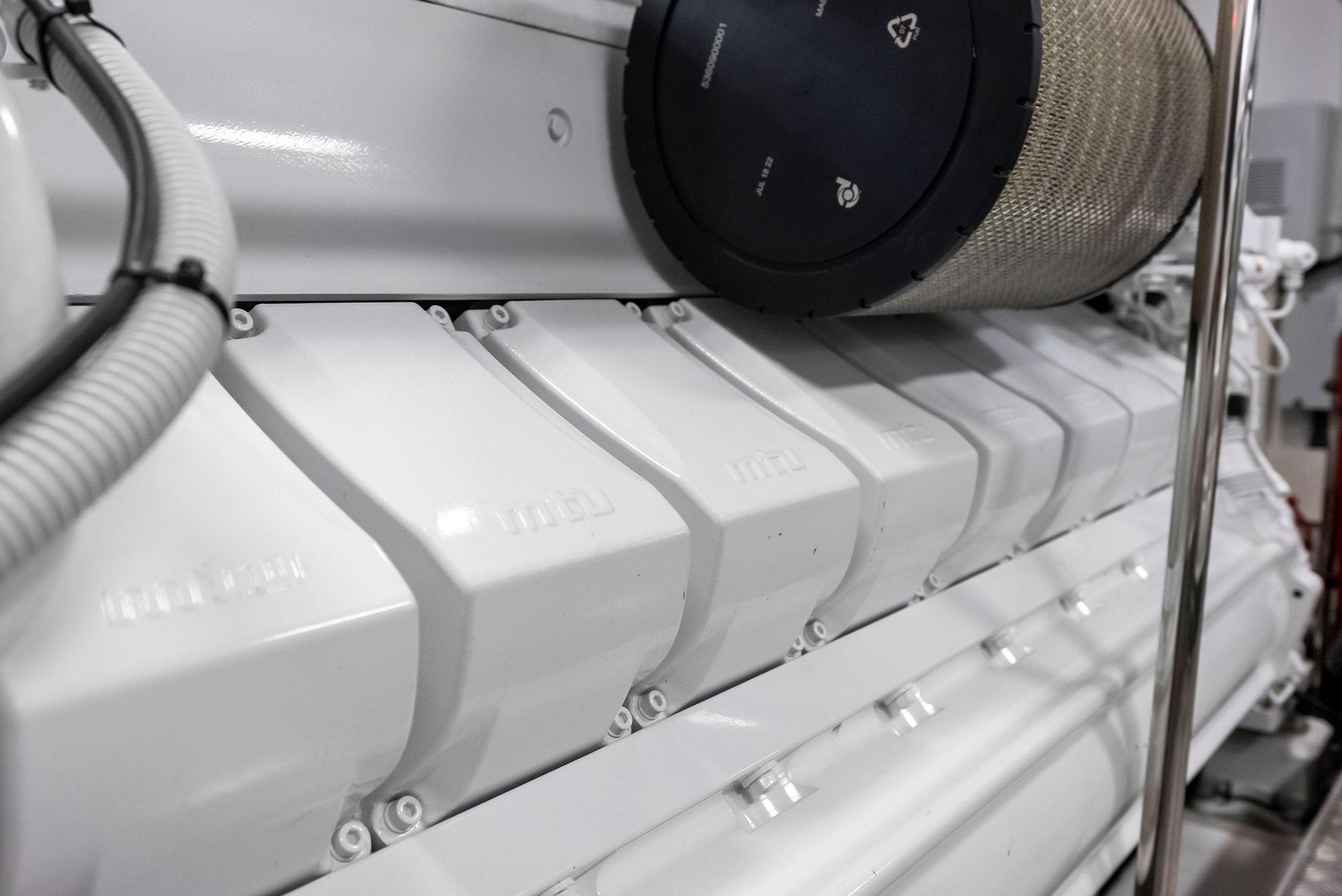
MAIN ENGINES
Two four stroke diesel engines suitable for marine propulsion are installed on foundations in the engine room, one on each side:
Manufacturer: MTUModel: 16v 2000 M96LRated power (each): 2638 mhp / 1939 kW @ 2450 RPM.Rated power is according with the manufacture operating profile 1DS (average power: less than 60% of rated power / annual usage: up to 1000 hours). Exhaust emissions in compliance with IMO II / EPA TIER 3 regulations.
GEAR BOXES
Each engine has a reduction gear box ZF 3070A. Reduction ratio determined on relation to the propeller design and propulsion set is 2.750:1.
SHAFT LINES, BEARINGS AND SEALS
Sea water lubricated bearings are installed for each propulsion shaft line. Shaft material is made of Marinox17.
Mechanical seals are mounted inside the hull, they are cooled by the seawater system.
On the propeller side each shaft is supported by one custom designed single strut, constructed in NiBrAl and designed according to the Classification Rules. The support is completed by a bossing in heavy thickness tube. A hydro-lubricated rubber bearing is fitted into the bossing.
PROPELLERS
Two skewed propellers, 5 blades, diameter about 1250mm, designed to obtain high efficiency and low noise will be provided. They are made by nickel- aluminum-bronze (NiBrAl). Each propeller is statically and dynamically balanced. Manufacturing tolerances will be according to ISO 484/2 CLASS S.
RUDDERS
Two spade rudders with drive by wire steering control are installed. The blade size is determined to ensure good maneuvering capabilities; the rudder is properly transversally off-set from shaft line axis in order to remove the screw shaft without dismounting the blade. The rudders construction material is AISI 316L. Rudder holes are in stainless steel, rudder stock is made of Marinox17.
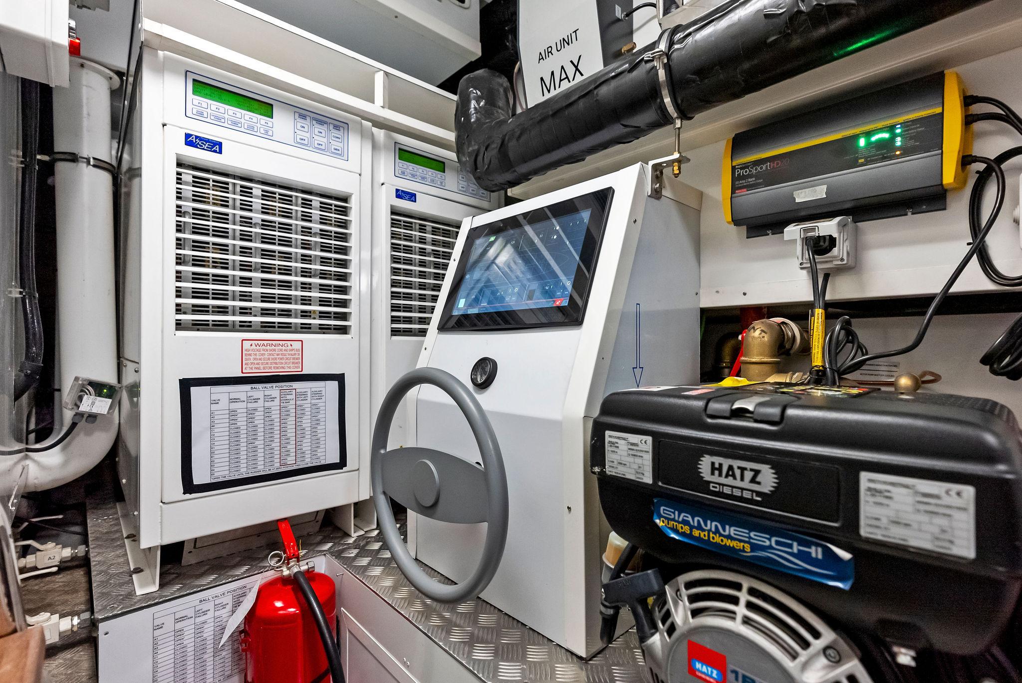
STEERING
The steering system is of electrohydraulic type. A drive by wire steering wheel are fitted in the wheelhouse and on the Fly helm station. On the dashboard a control panel shows the main info (mode, alarm status, rudder angle) of the steering system. The hydraulic system is made of one power pack (oil reservoir with a 400V/50Hz/3ph pump) and 2 hydraulic cylinders (one for each rudder).
BOW THRUSTER
A bow thruster unit driven by a 58Hp hydraulic motor is installed in a dedicated space. The installation is executed strictly according to Manufacturer instructions and specifications. Control Joystick are installed on both wheelhouse main and fly helm stations.
STABILIZER FINS
Two electro hydraulic stabilizer fins working underway and at zero speed have been installed. The fins control is integrated in the main dashboard with additional control panel for backup in wheel house.
INTERCEPTORS
Two units, one for each side, is installed on the transom edge actuated by servo units connected with control units. The system is governed by the monitoring system in the wheelhouse.
ELECTRIC POWER GENSETS
Two diesel generators with the following characteristics are installed in the engine room:
• Manufacturer Kohler• Rated power outputs: 44kW• Rated voltage / frequency and phases: 400Vac/50Hz – 3 phase• RPM 1500• Insulation class: H• Tension regulation: ±0.5 %• Frequency regulation: ±0.5 %• Starting system: 24 Vdc
Each diesel genset is provided with automatic shut-down for the following alarms:
• Low oil pressure• High water temperature• Overspeed
Each diesel genset is equipped with:
• Sound-proof enclosure and white paint RAL according to the Maker's standard.• Resilient support system.• Built-in freshwater circulating and cooling system with heat exchanger• oil cooler.• Electronic speed regulators.• Control panel installed outside the soundbox equipped with: – Starting/stop push buttons – Volts, amps and hour meters
Exhaust gas system are wet type, with a gas water separator and outlet installed on the hull side shell at waterline level; pipes to gas/water separator and between gas/water separator and outboard are in CuNi. The gensets installation is done strictly according to Manufacturer instructions and specifications.
Systems
BILGE AND FIRE FIGHTING SYSTEM
FIRE FIGHTING SYSTEM
• n°1 on sun deck• n°2 on main deck• n°4 on the lower deck
BILGE PUMP
FIRE FIGHTING PUMP
EMERGENCY DIESEL MOTOR PUMP
One diesel motor pump with a flow rate of max 550 l/min and a manometric head of max 40m H2O is installed, in the control room.
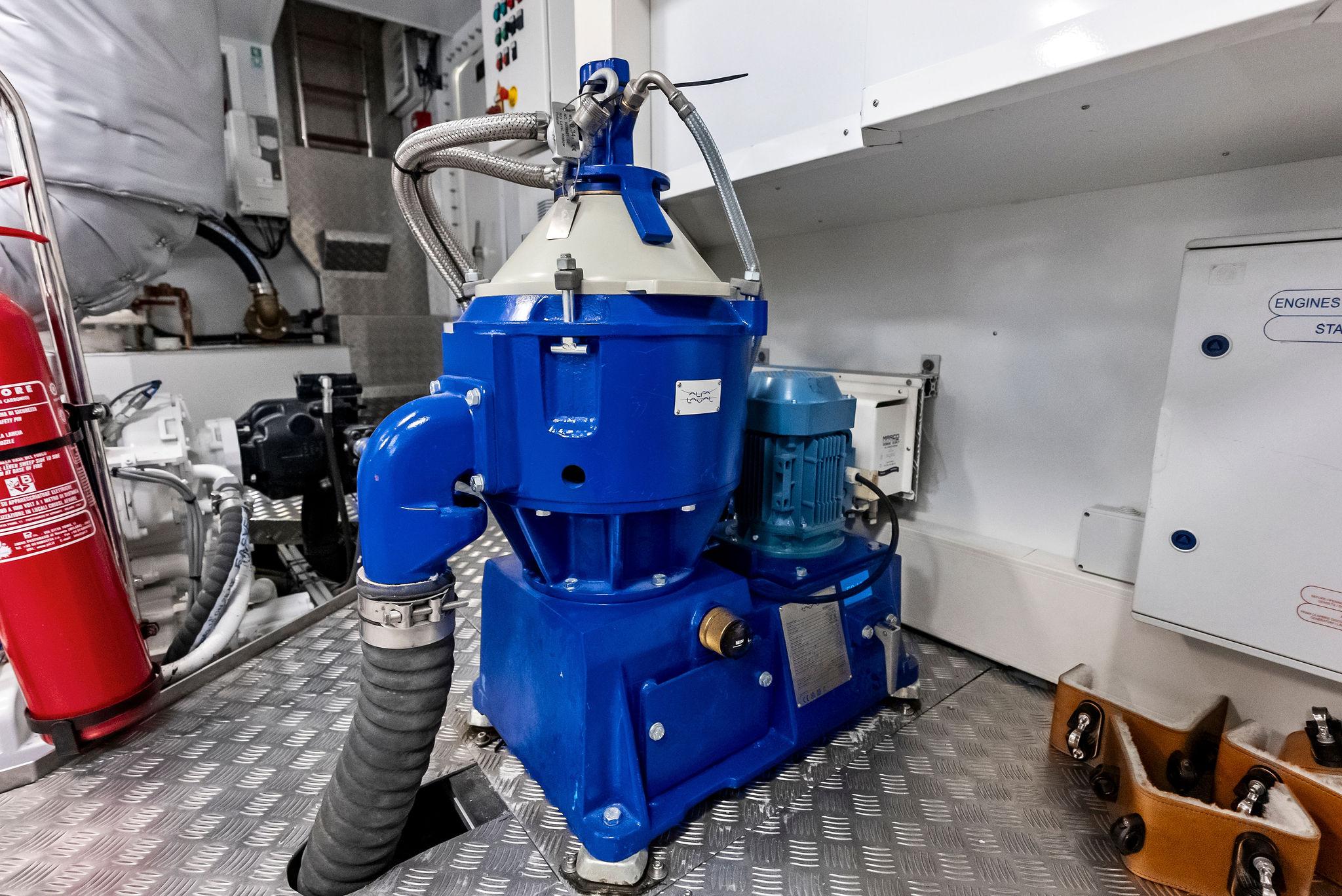
FUEL OIL SYSTEM
FUEL OIL TRANSFER PUMP
FUEL OIL FILTERS
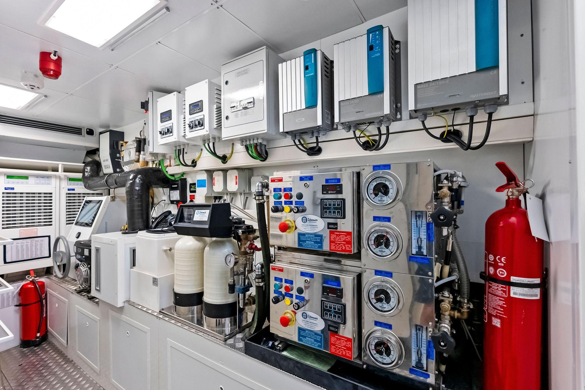
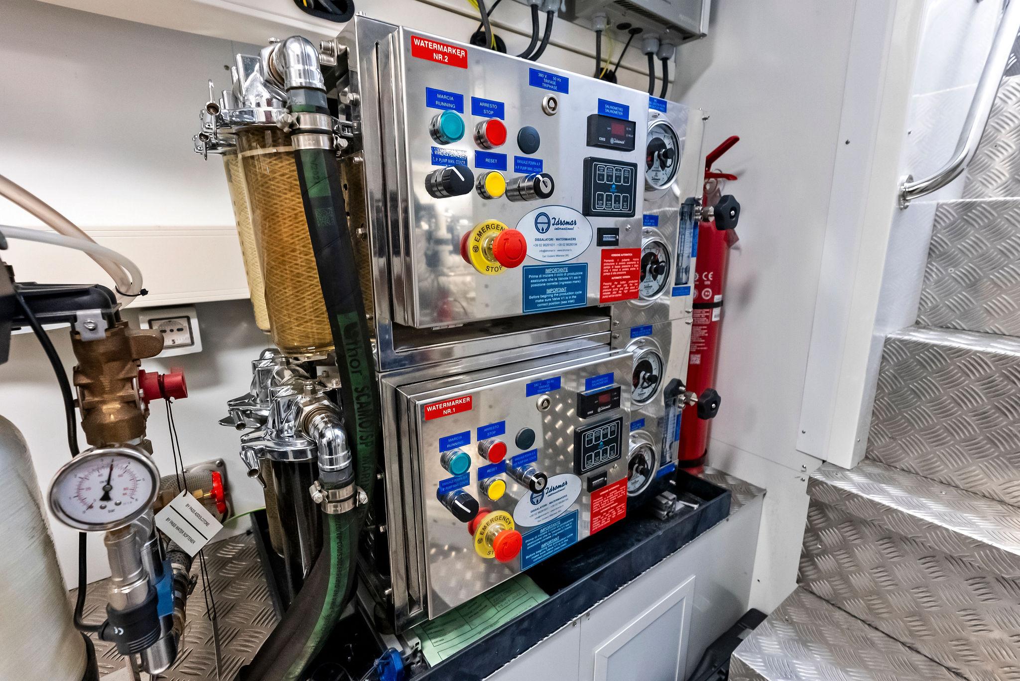
FRESH WATER SYSTEM
FRESH WATER MAKER
FRESH WATER PUMP
SEWAGE SYSTEM
BLACK AND GREY WATER PUMPS
FIRE EXTINGUISHING SYSTEM
ENGINE ROOM EXTINGUISHING SYSTEM
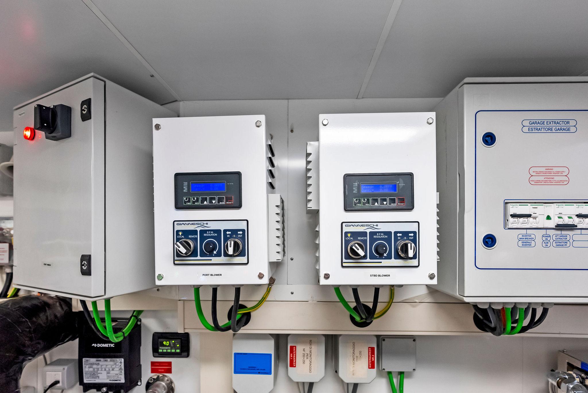
GARAGE EXTINGUISHING SYSTEM
COMPRESSED AIR SYSTEM
SCUPPERS AND DRAINAGE SYSTEM
SEA WATER COOLING SYSTEM
AIR VENT LINES
HYDRAULIC SYSTEM
The systems consist of the power packs feeding the following systems, where in-stalled:
MAIN ENGINES GAS EXHAUST SYSTEM
AIR CONDITIONING SYSTEM
Designed and built in such a way as to guarantee comfort in weather conditions . Interior living spaces such as cabins, saloons, wheelhouse served by the air conditioning system. The yacht ventilation system is based on the following principles:
Outfittings
ANCHOR AND MOORING EQUIPMENT
MOORING BOLLARDS
FAIRLEAD
Polished stainless steel AISI 316L fairleads will be fitted in bulwark as follows:• n. 2 on the forward maneuvering area, equipped with 3 vertical rollers each (1 for each side)• n. 4 with integrated hooks, fitted on the side bulwark (2 for each side)• n. 2 on the aft bulwark in way of the raised mooring area equipped with 3 vertical rollers each (1 for each side)
WINDLASSES
CAPSTANS
FENDERS AND WHIPS
DOCKING LINES
GANGWAY
SWIMMING LADDER
AFT GARAGE AND TENDER
FORWARD GARAGE
GLASS WINDOWS
PORTHOLES
WATERTIGHT DOORS
BULWARK DOORS AND AFT GATES
EXTERIOR DOORS AND HATCHES
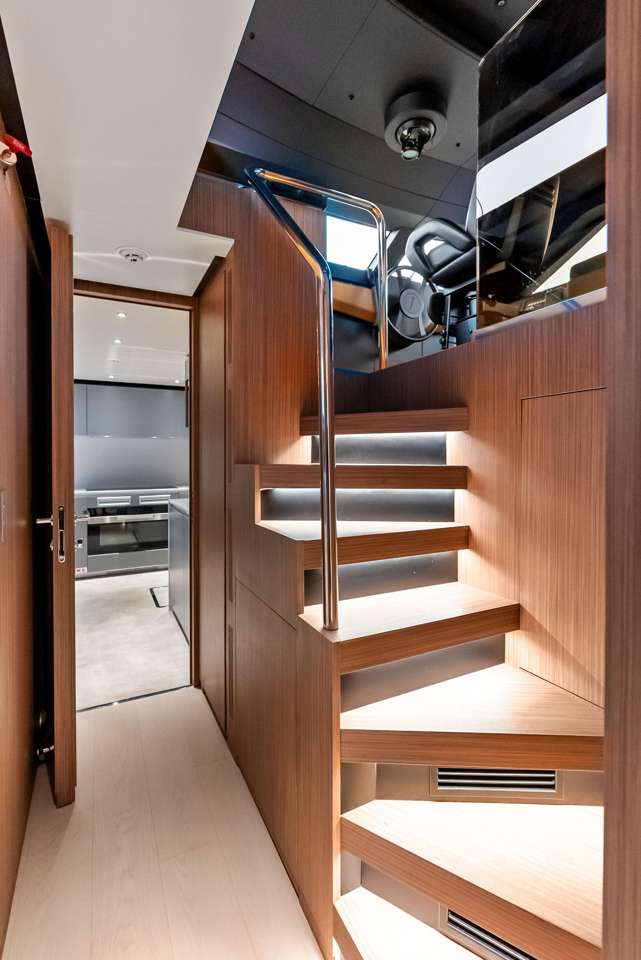
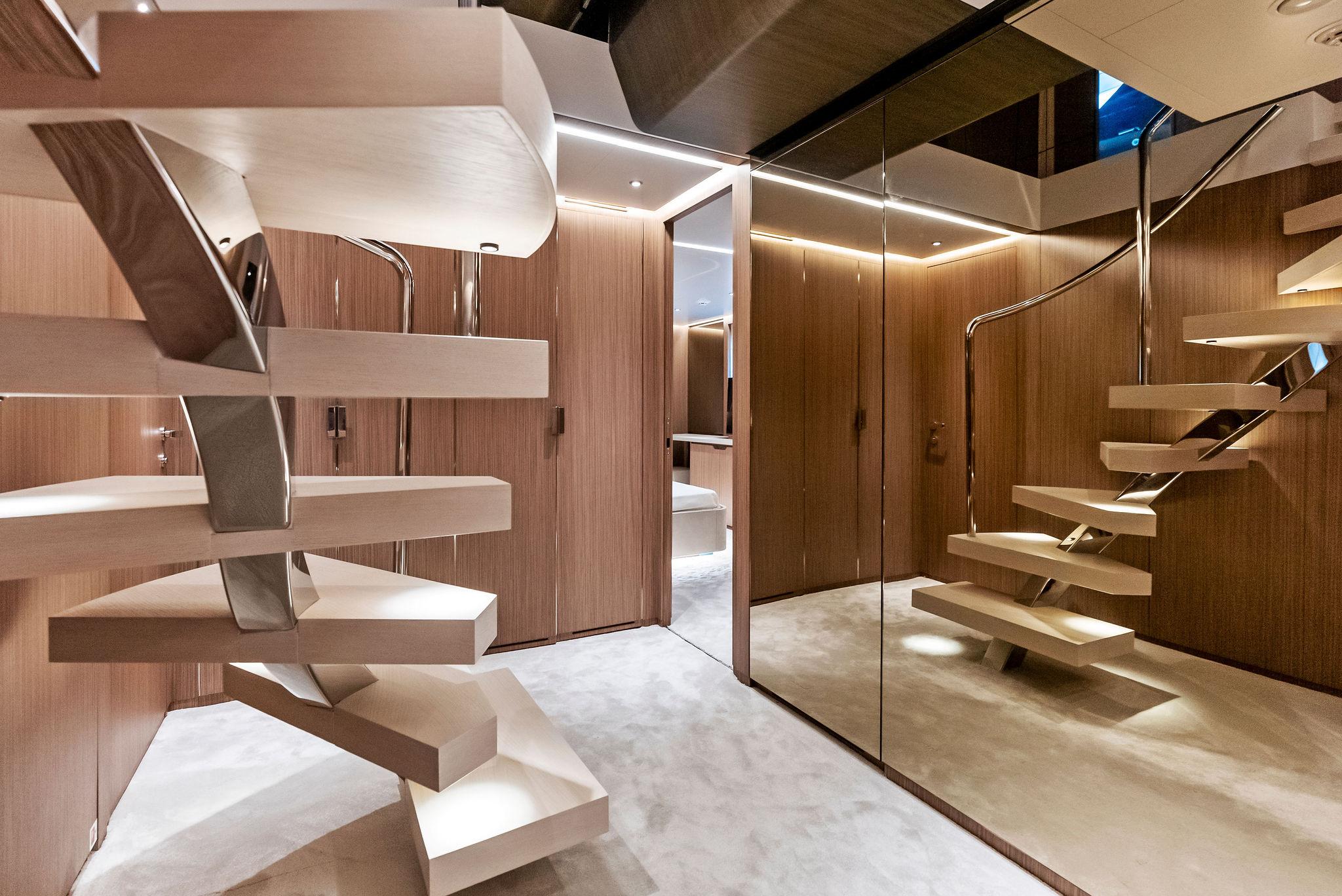
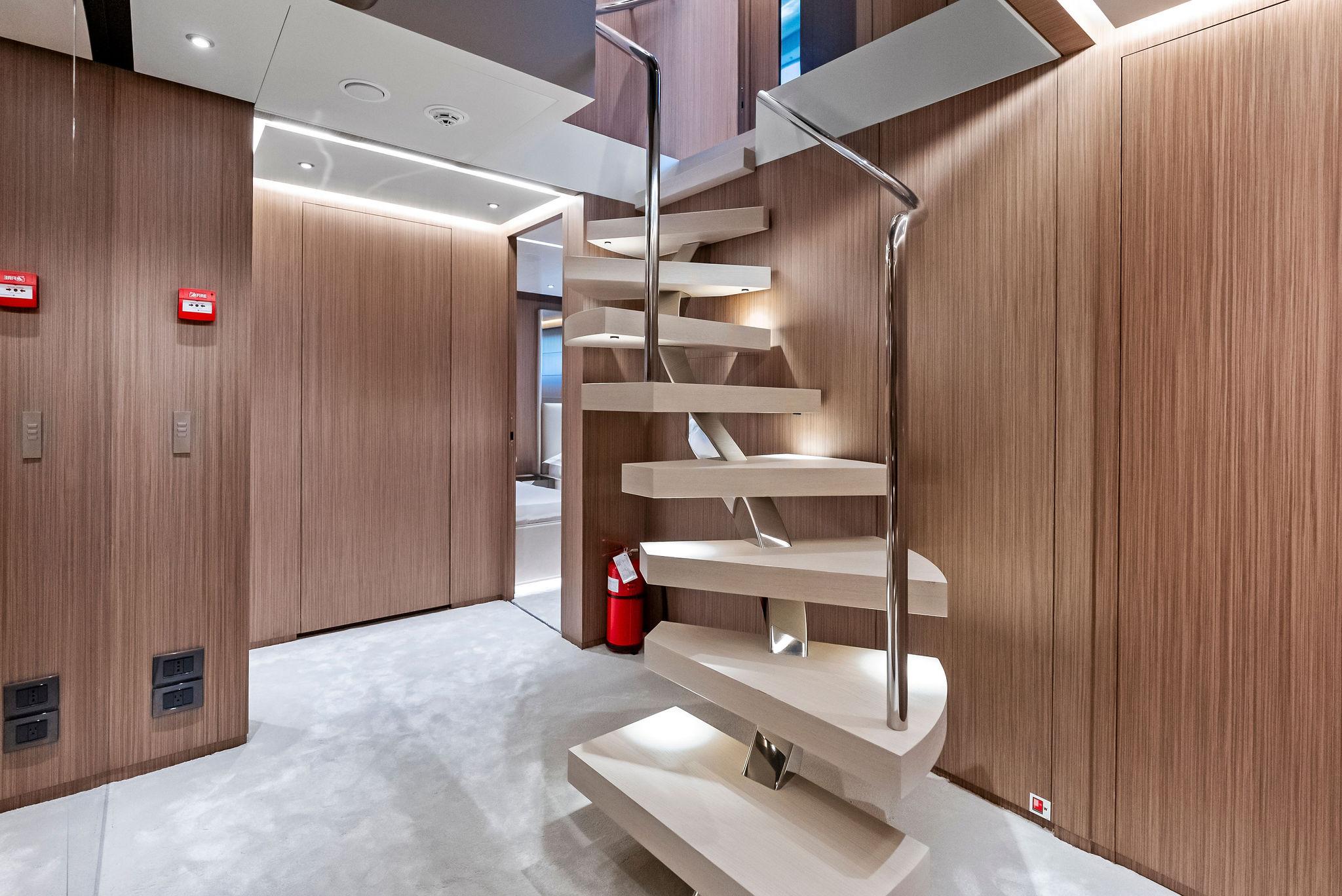
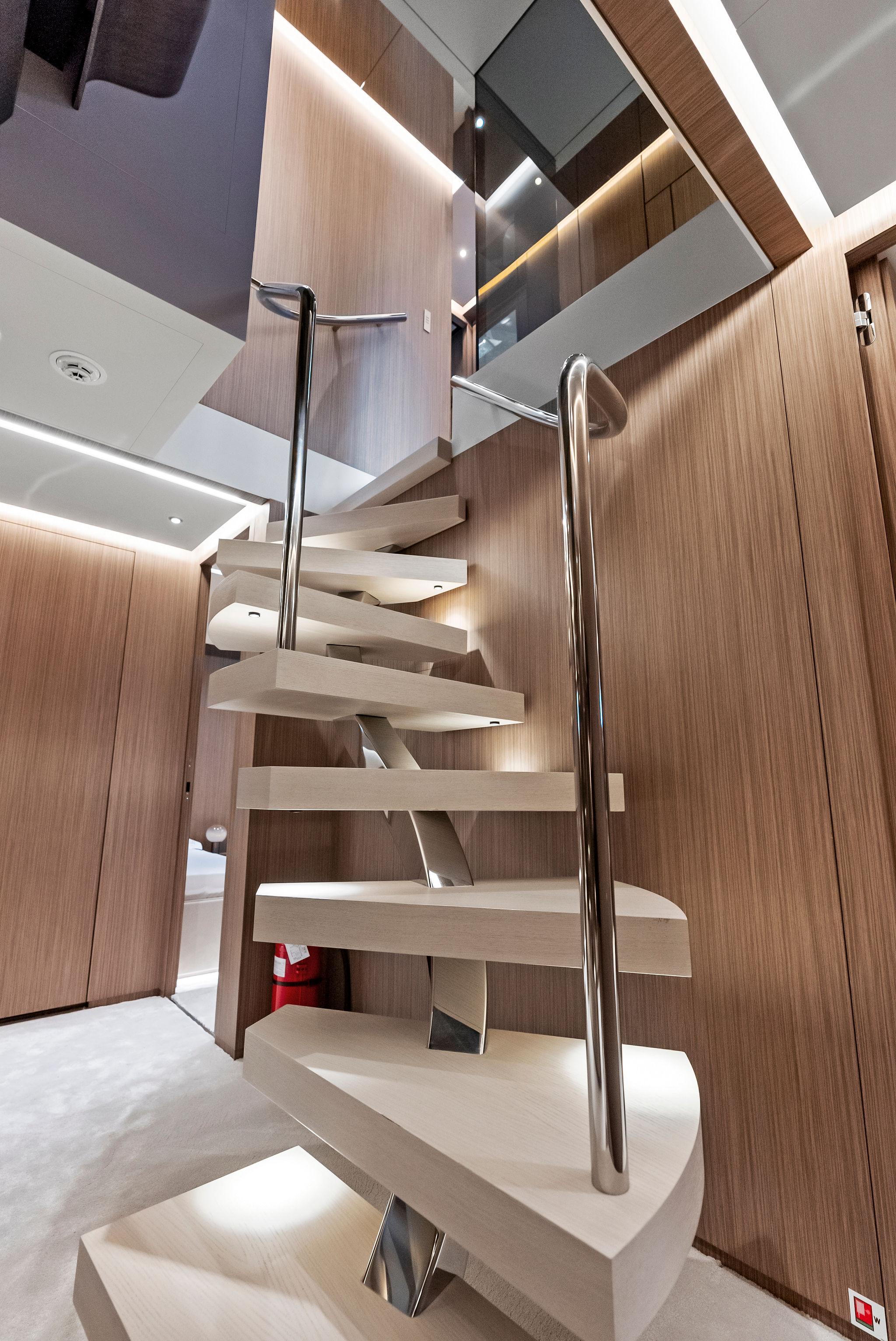
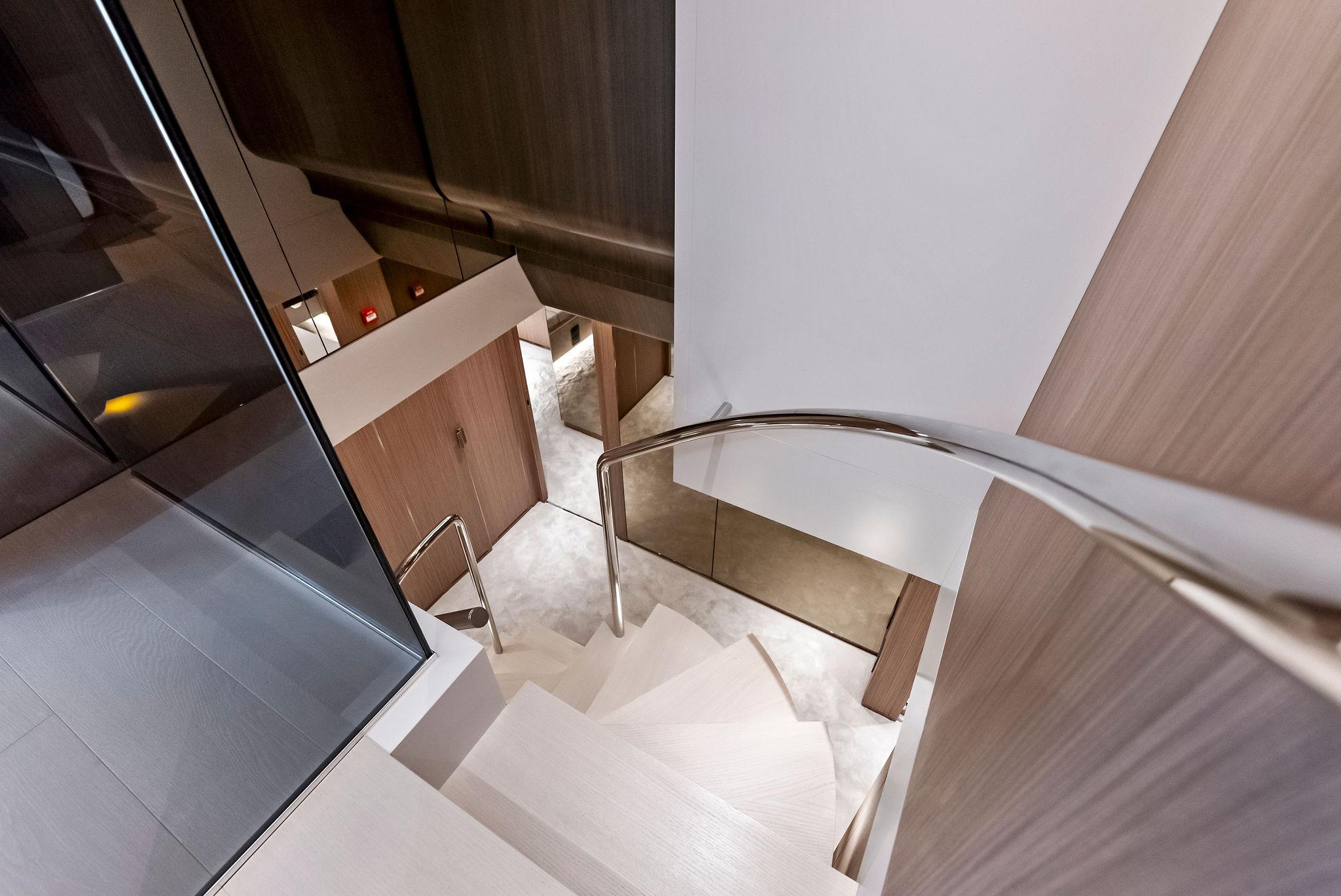
HANDRAILS, CAPRAILS, PILLARS AND EXTERNAL NON STRUCTURAL STAIRS
Polished stainless steel AISI 316L handrails, on the following areas:
TEAK DECK LINING
SAFETY EQUIPMENT
TENDER CRADLES
One set of plastic rollers for the tender inside the aft garage mounted on stainless steel frames bolted to the bottom plate.
SIDE TRACKWAYS
FLAGPOLES
WINDOW WIPERS
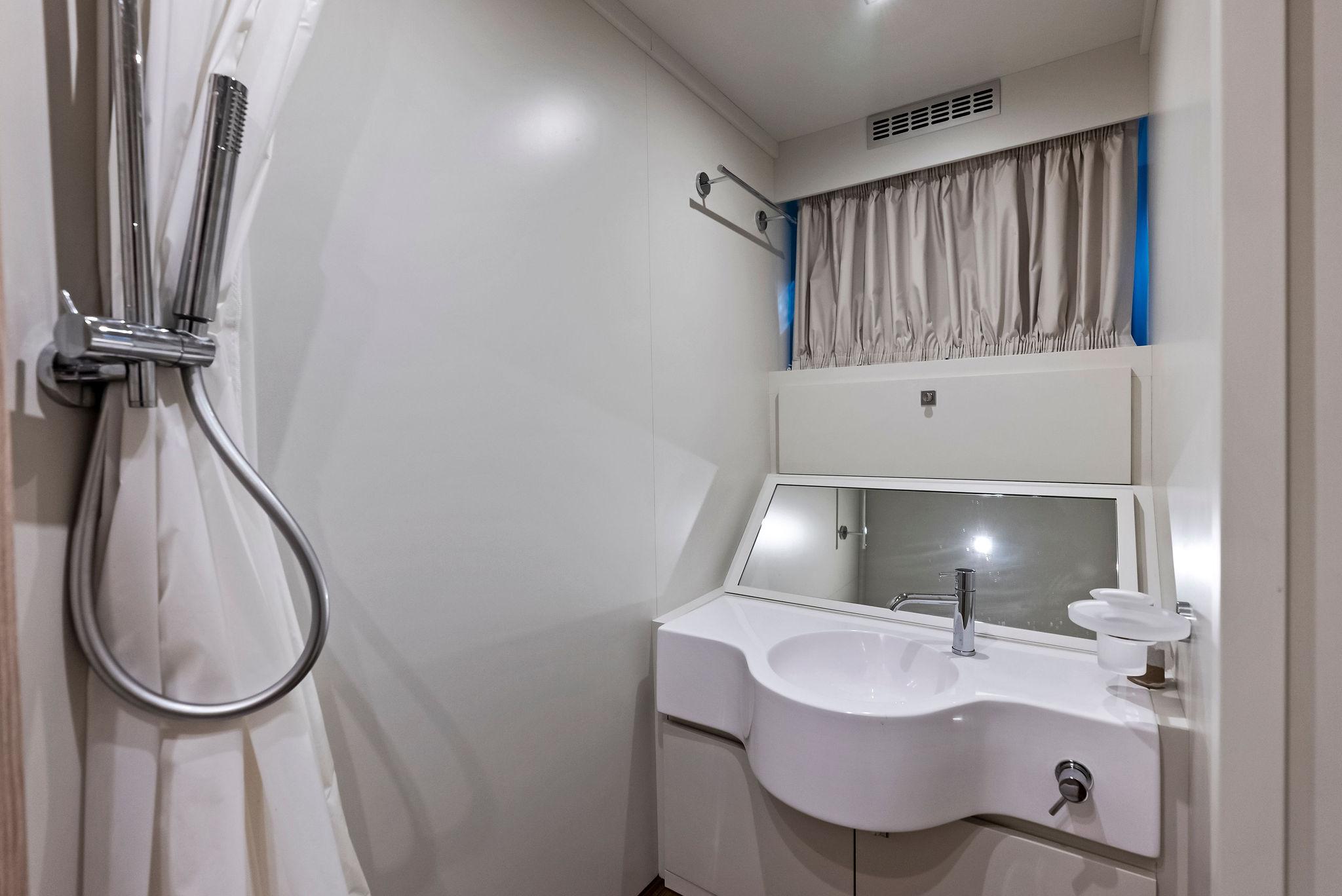
EXTERIOR SHOWERS
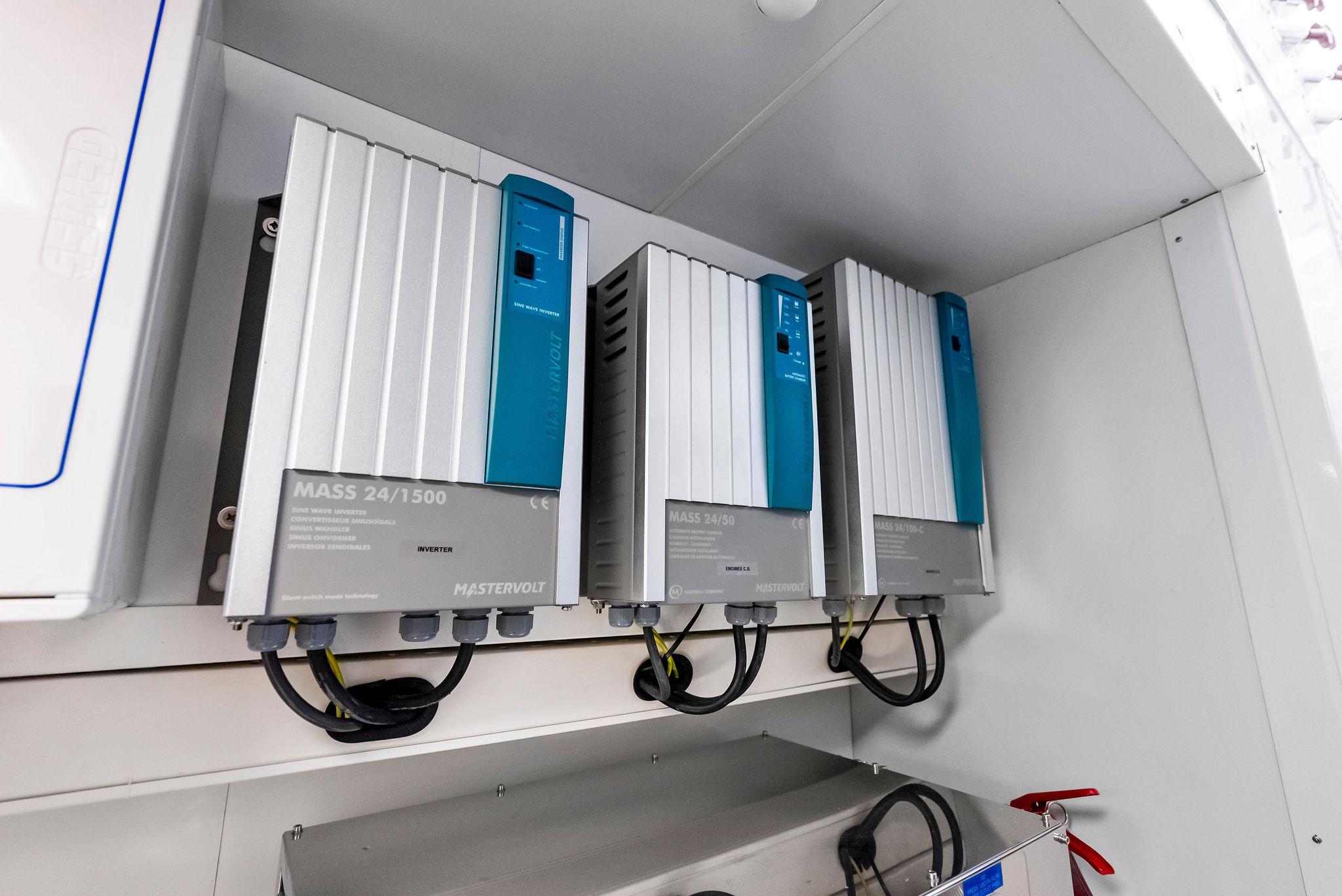
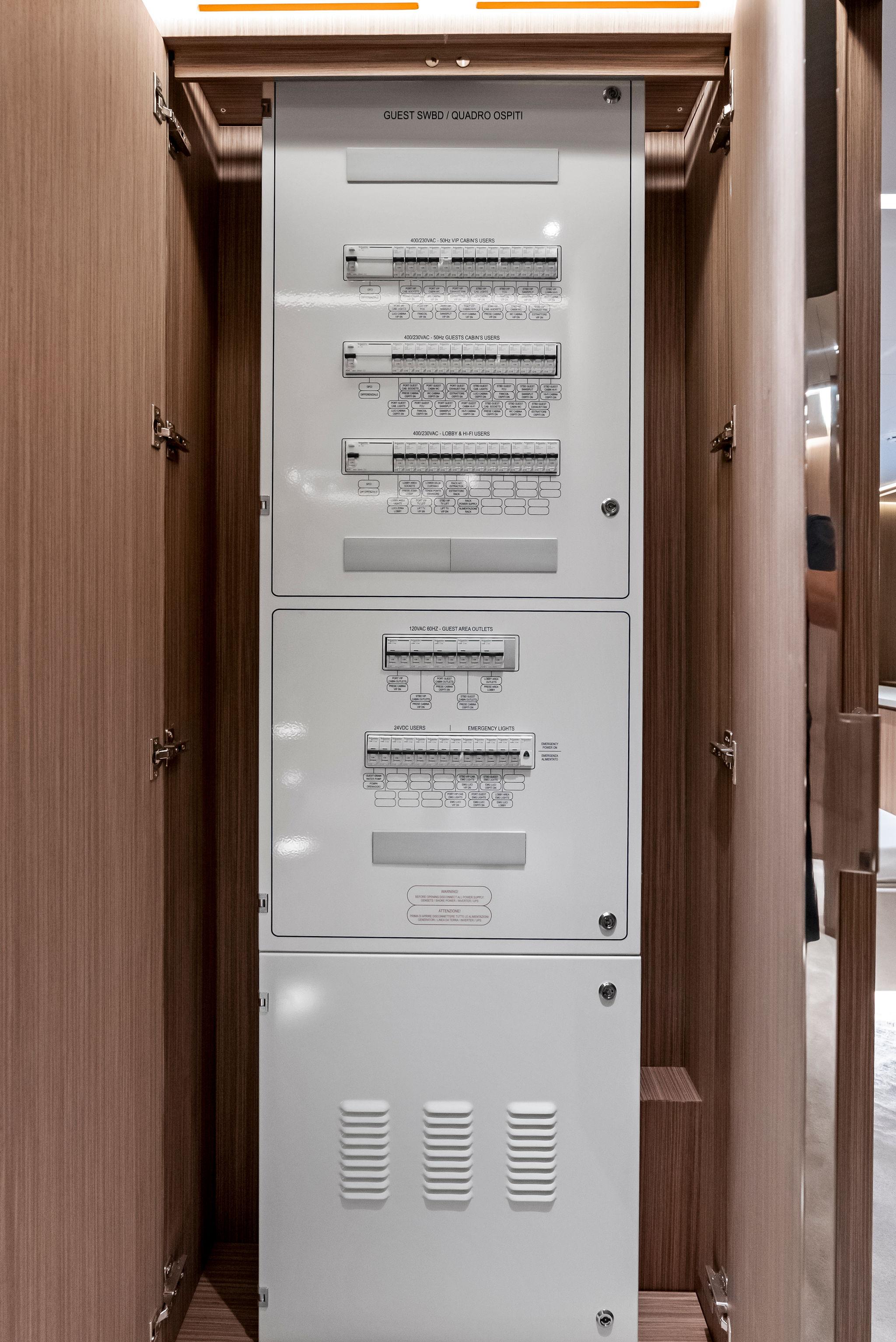
Electric System
POWER DISTRIBUTION
SHORE CONNECTION
MAIN SWITCHBOARD
EMERGENCY SWITCHBOARD
DISTRIBUTION SWITCHBOARDS
BATTERIES
ELECTRICAL MOTORS AND STARTERS
LIGHTING SYSTEM
TECHNICAL SPACES
WHEELHOUSE
CREW AREAS
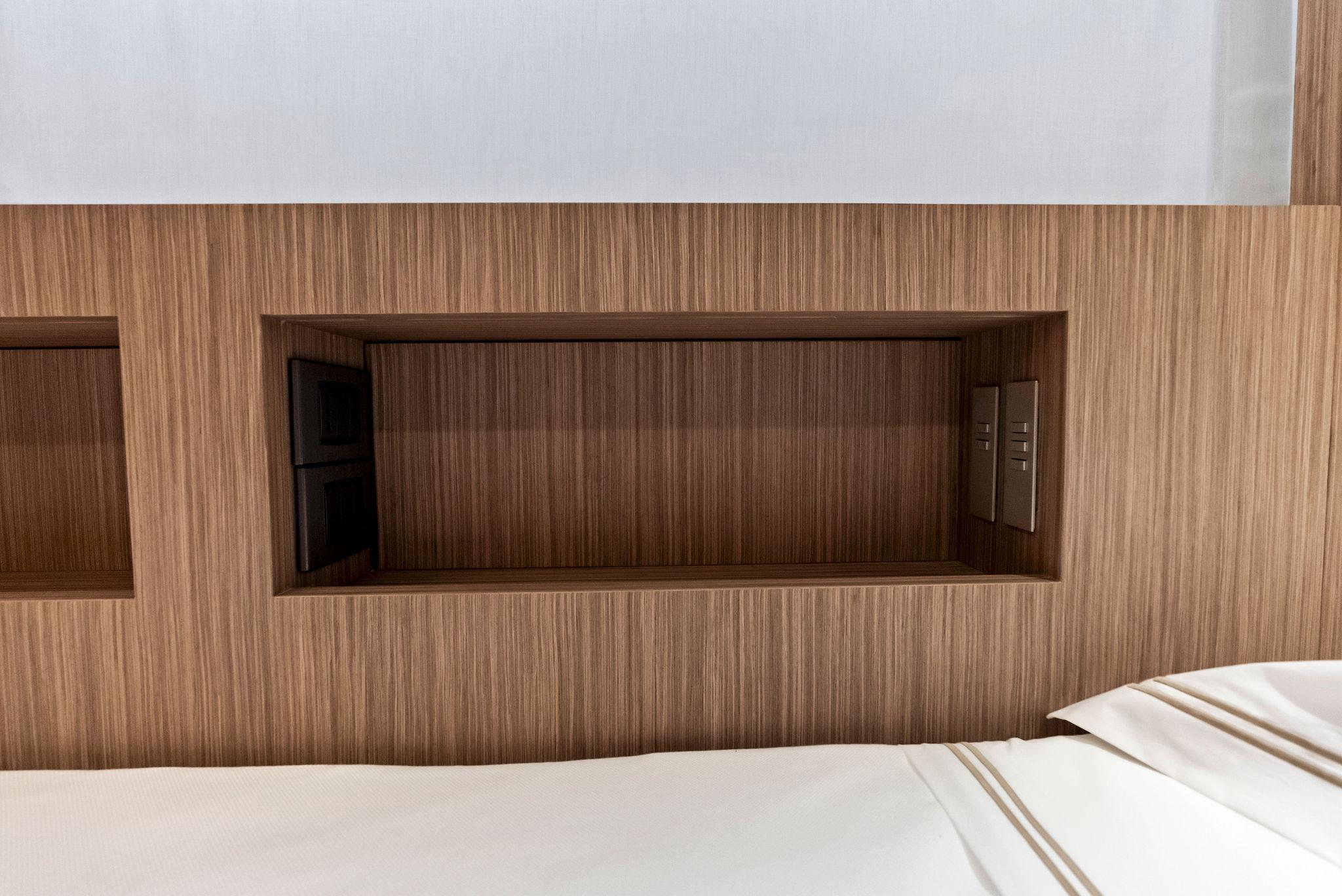
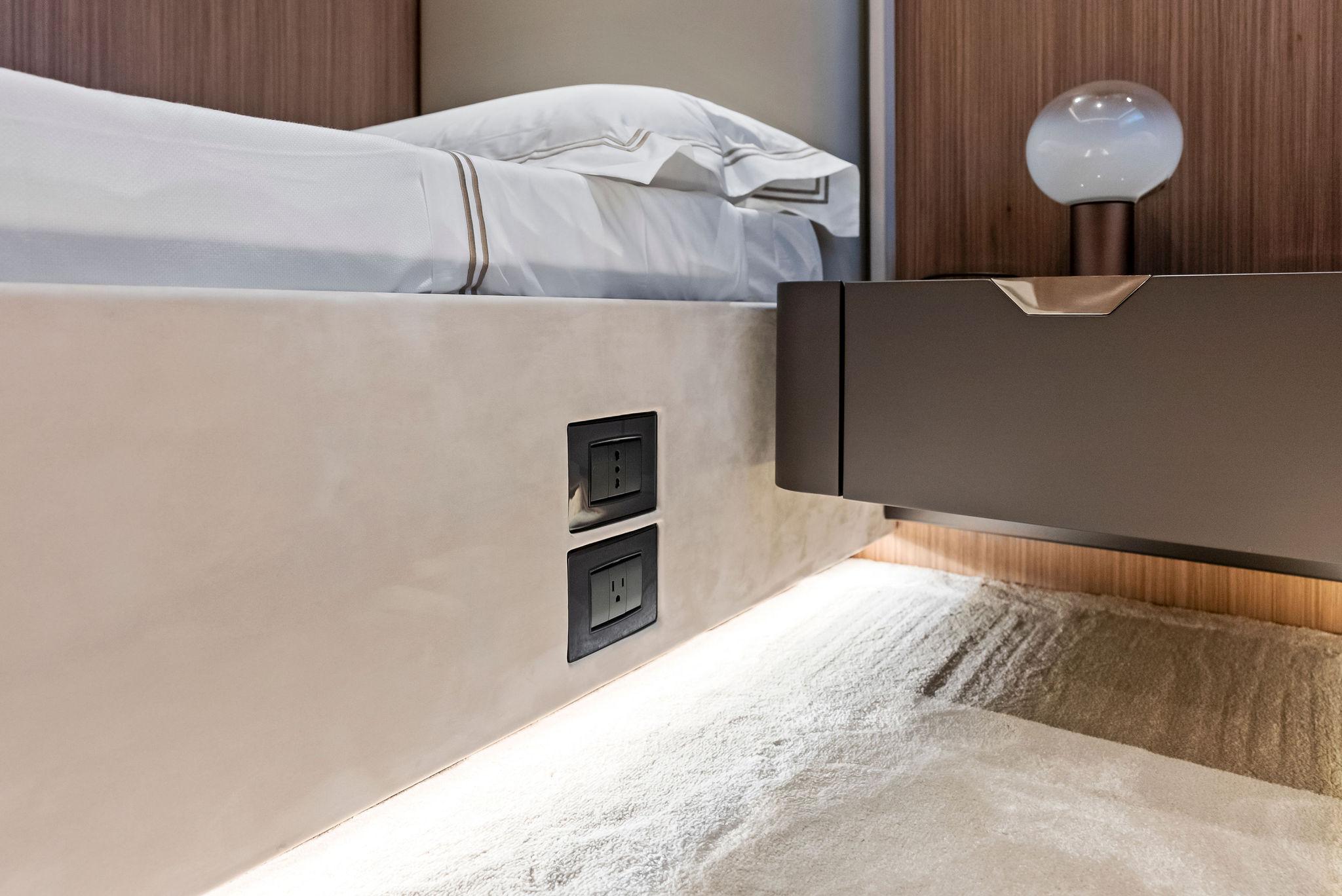
INTERIOR LIGHTING (VIP & BEACH CLUB)
SWITCHES, SOCKET OUTLETS AND RELATED COVERS
EXTERIOR LIGHTING
SEARCH LIGHT
UNDERWATER LIGHTS
EMERGENCY LIGHTS
FIXED FIRE DETECTION AND ALARM SYSTEM
Electronics / Entertainment
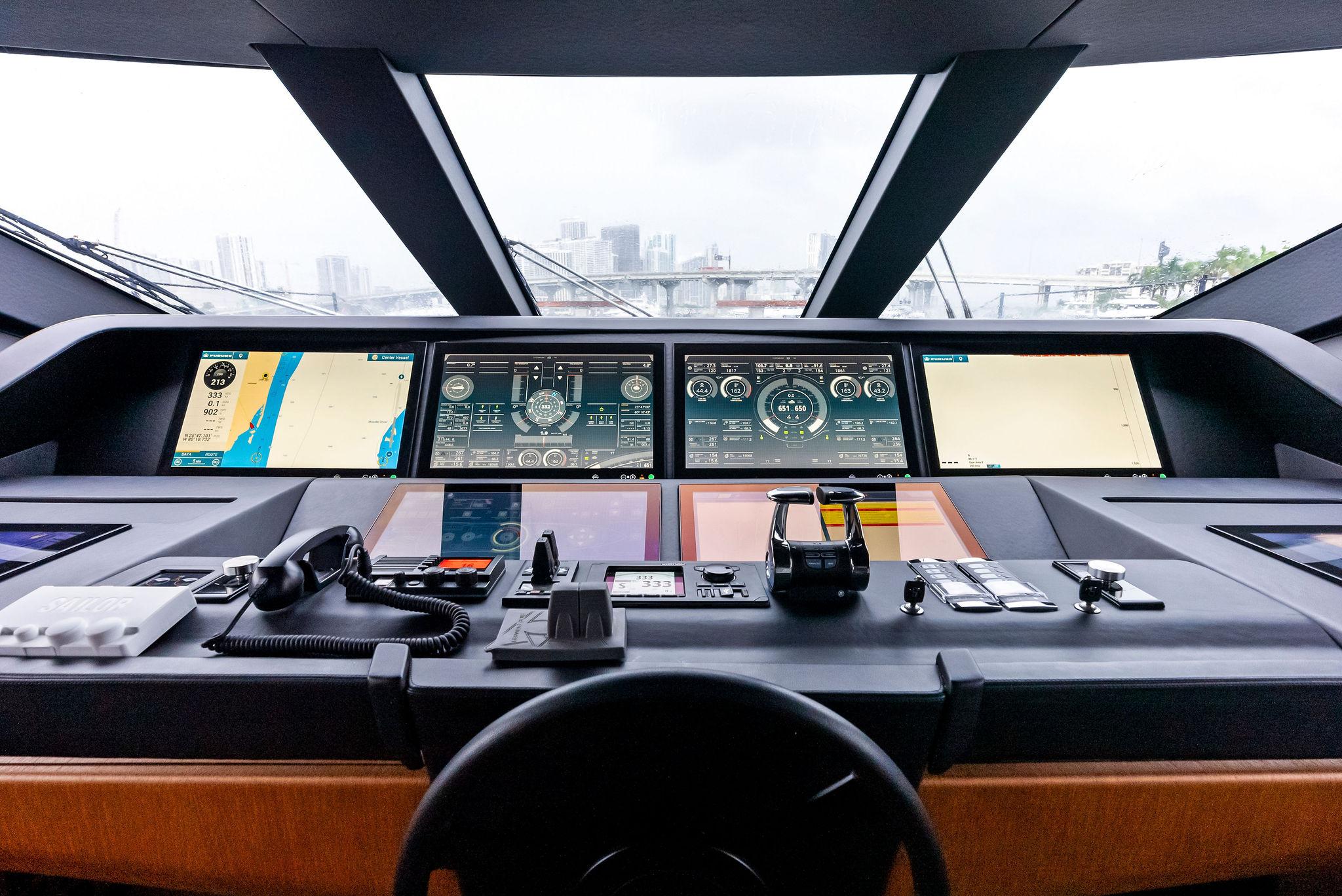
NAVIGATION SYSTEM
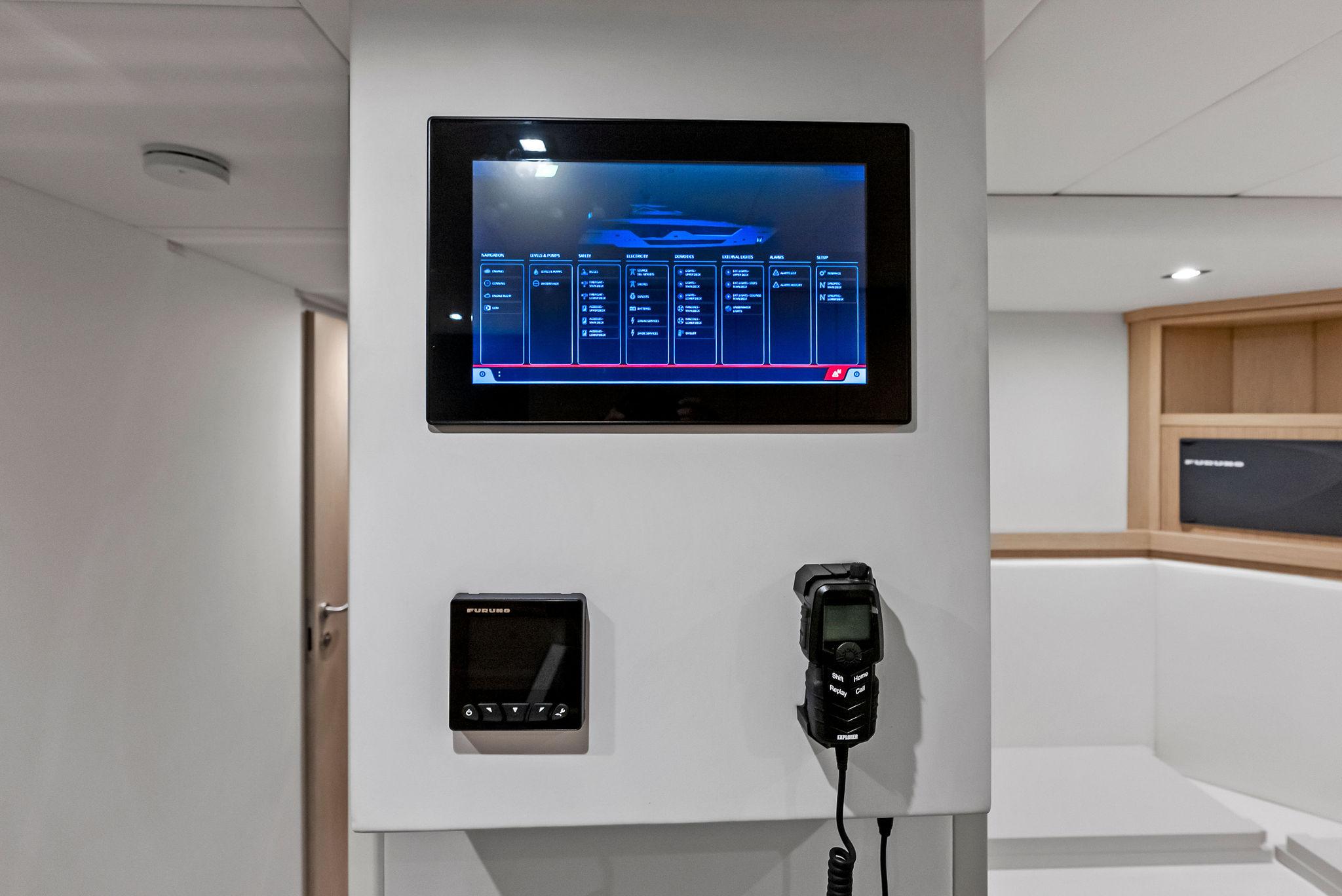
Innovative integrated dashboard with navigation and automation in the wheelhouse. The dashboard is composed by:
The integrated dashboard allows the visualization and control (where indicated) of the following items:
Additional stations:
Control stations positioned externally on sun deck and on the main deck aft cockpit, including the following commands:
NAVIGATION EQUIPMENT
NAVIGATION LIGHTS
HORN
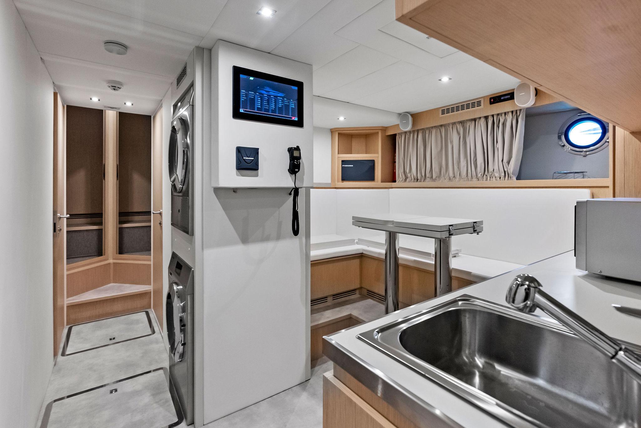
MONITORING SYSTEM
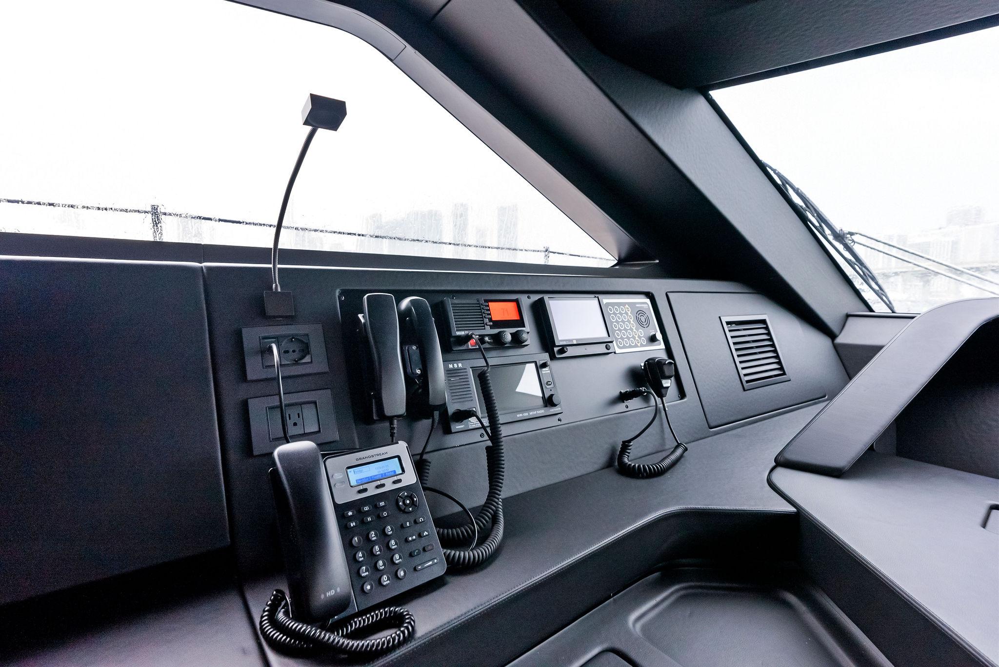
COMMUNICATION SYSTEM
NETWORK SYSTEM
INTERCOM SYSTEM
CCTV SYSTEM
ENTERTAINMENT SYSTEM AND IT
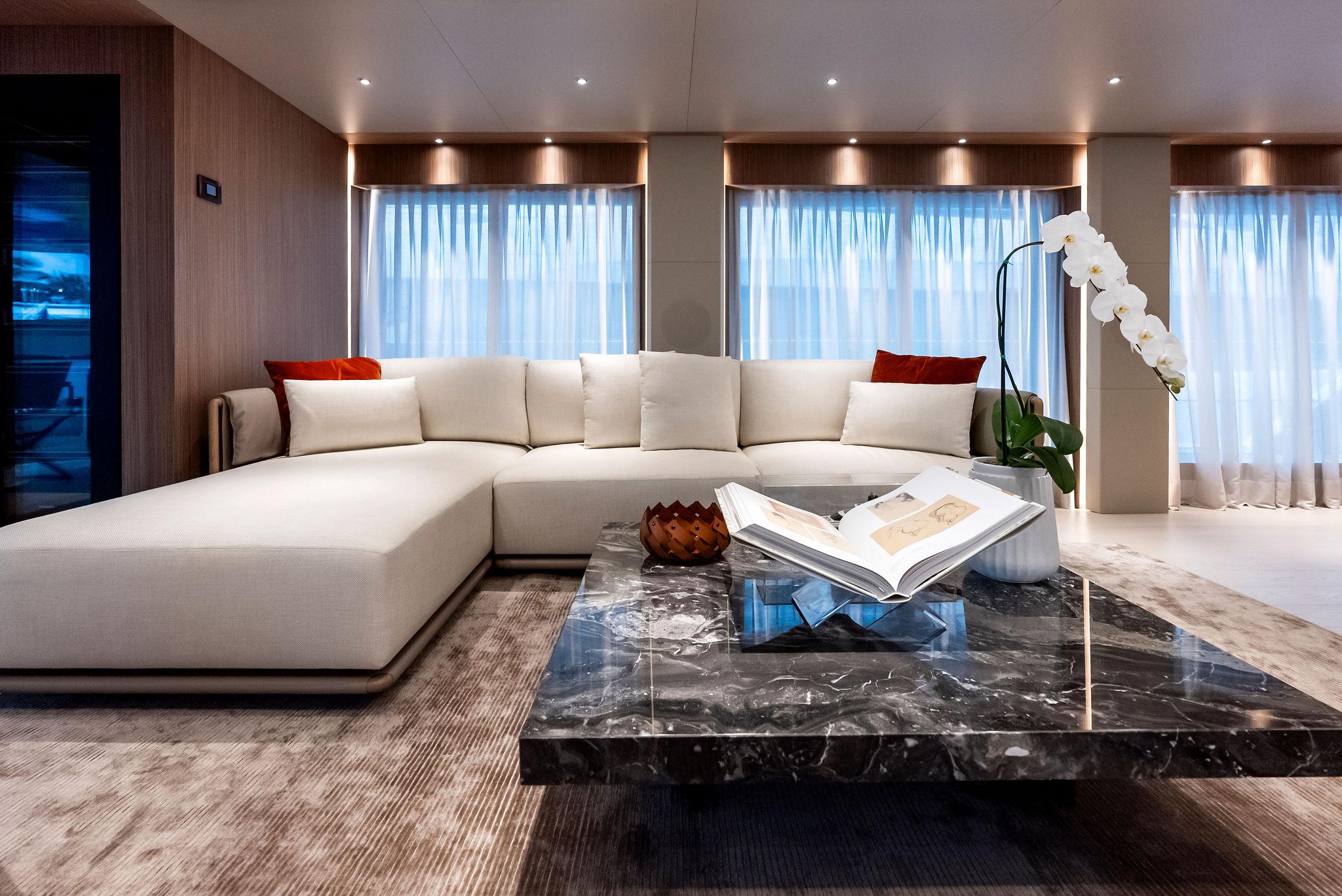
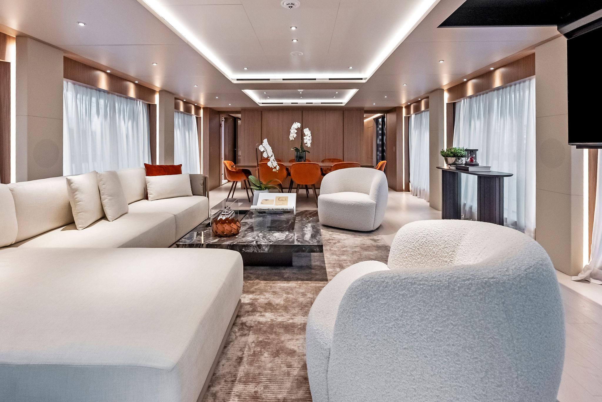
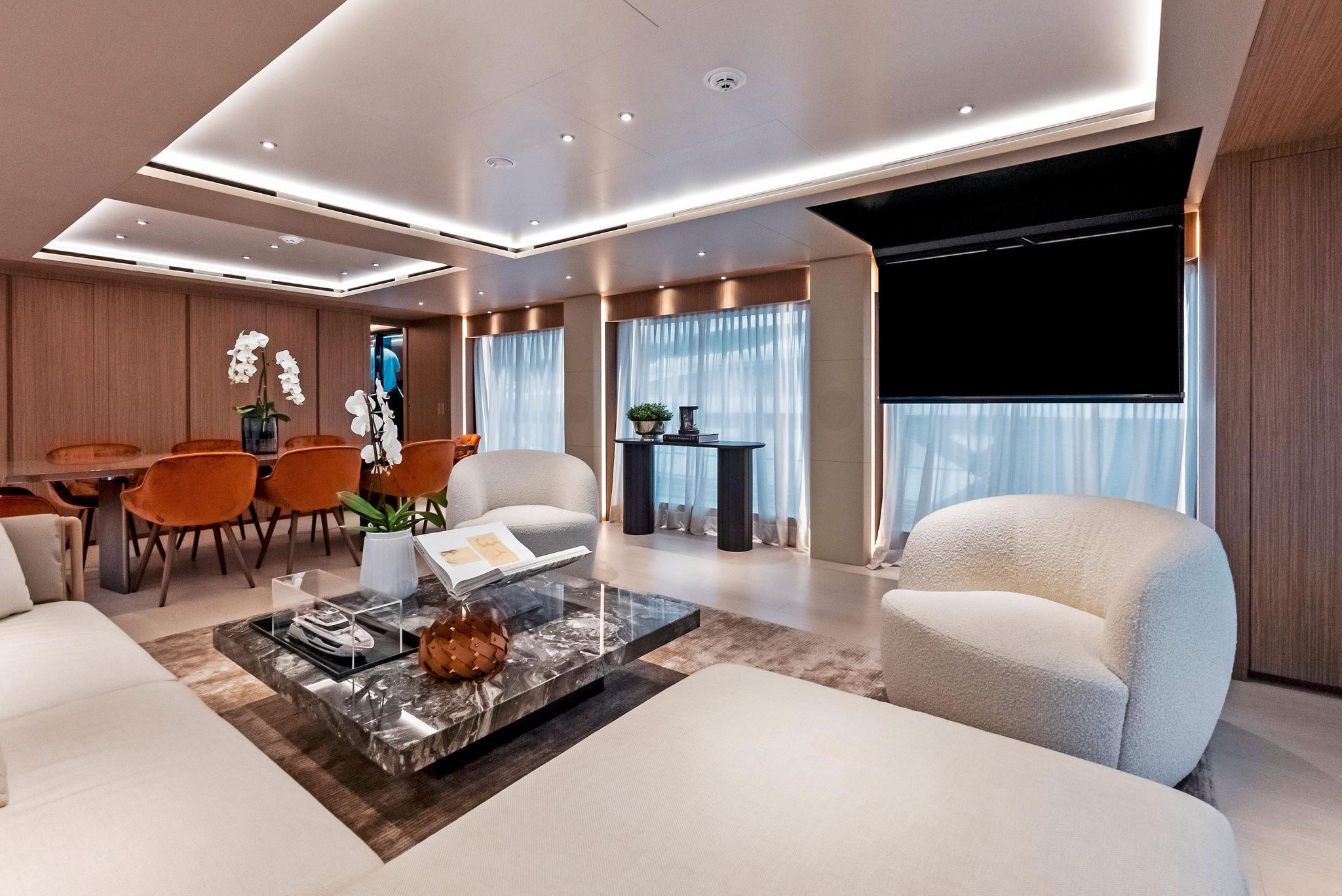
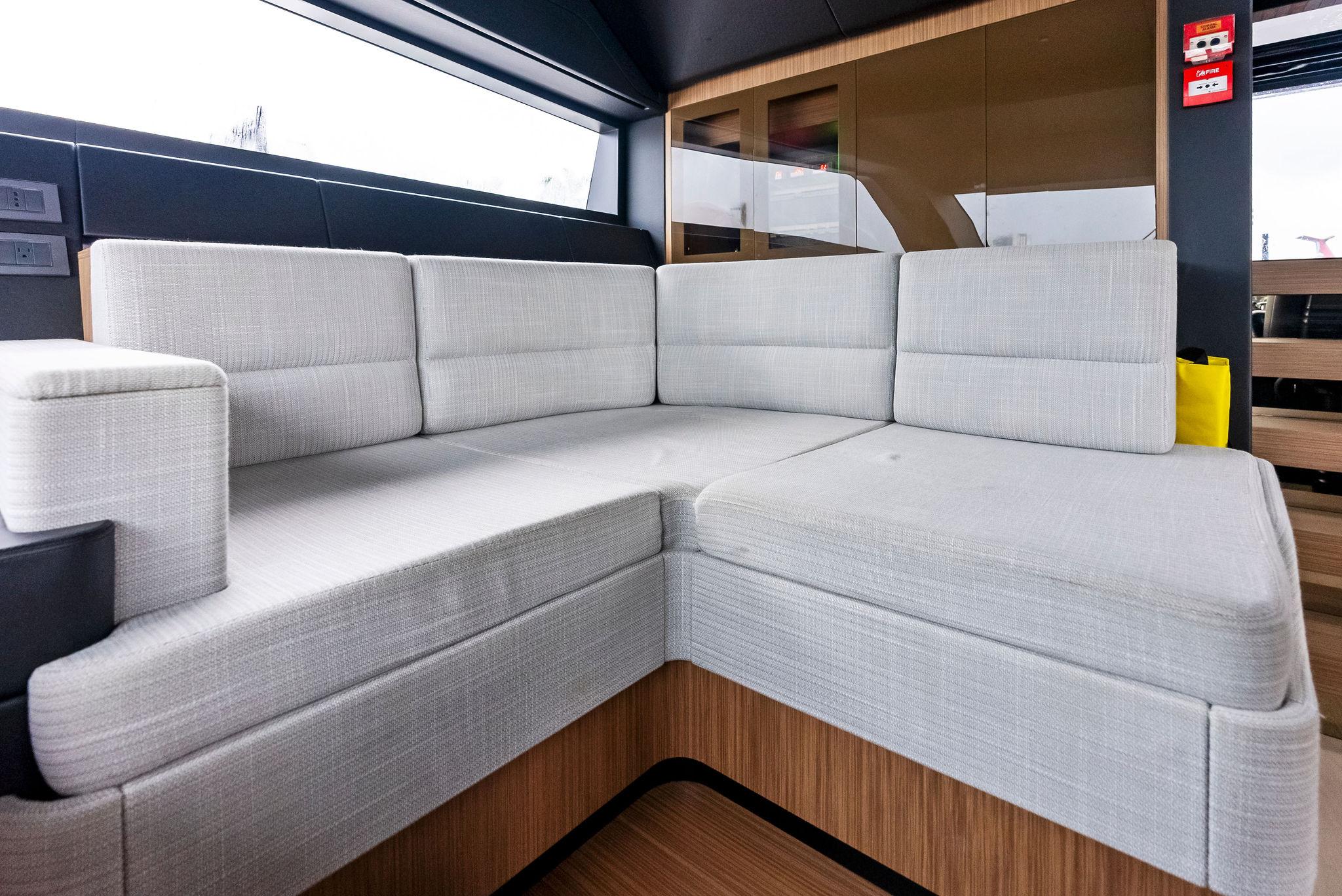
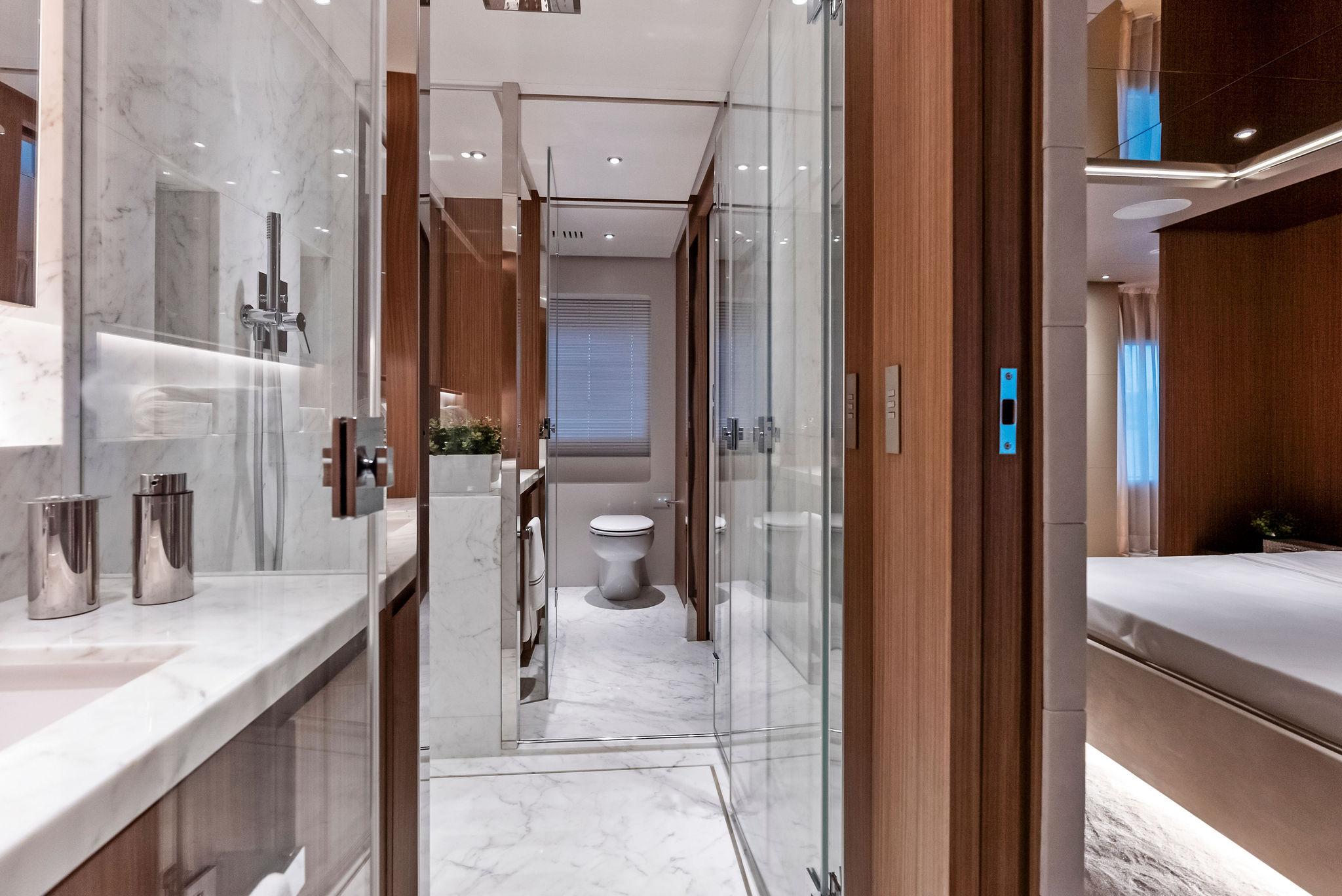
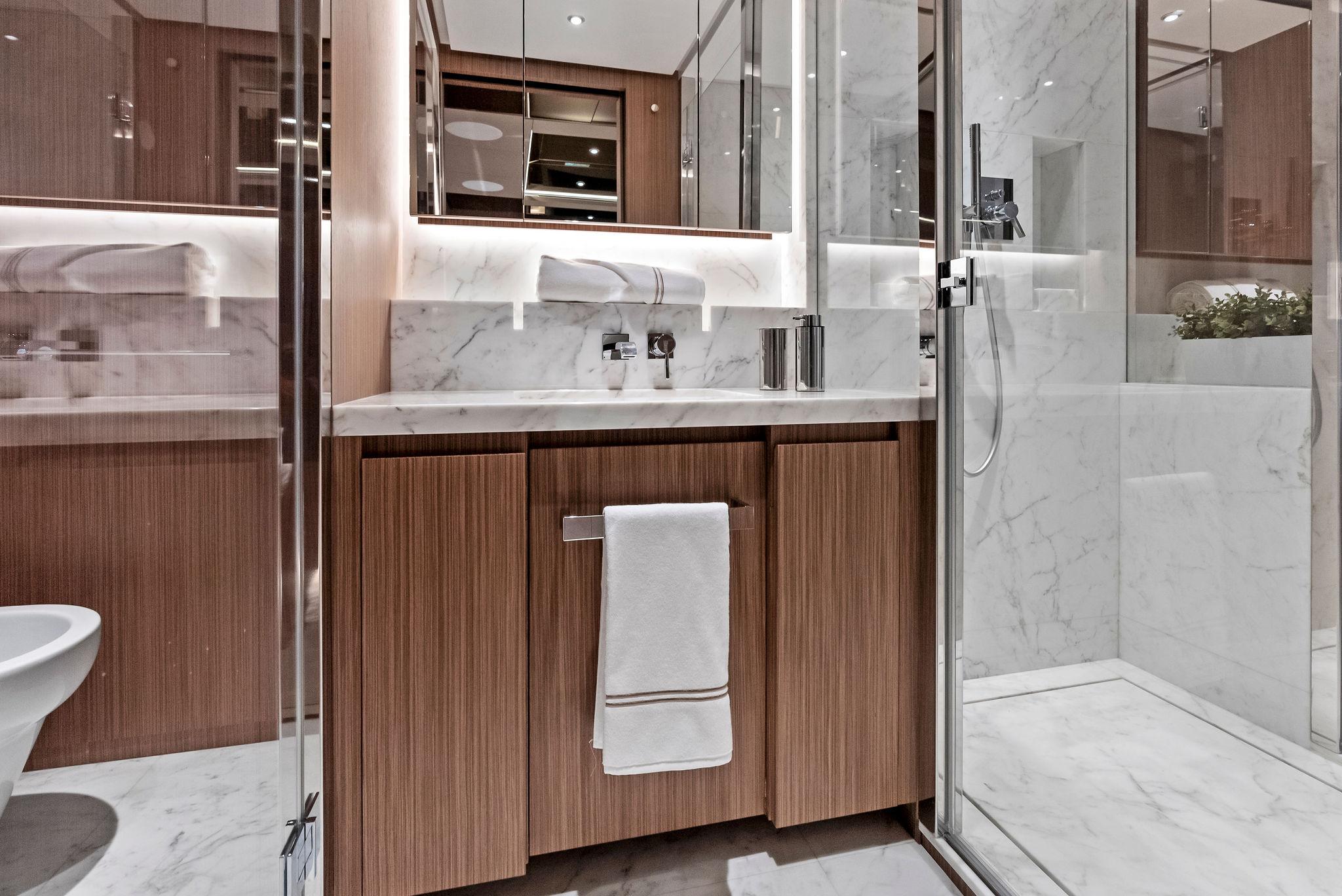
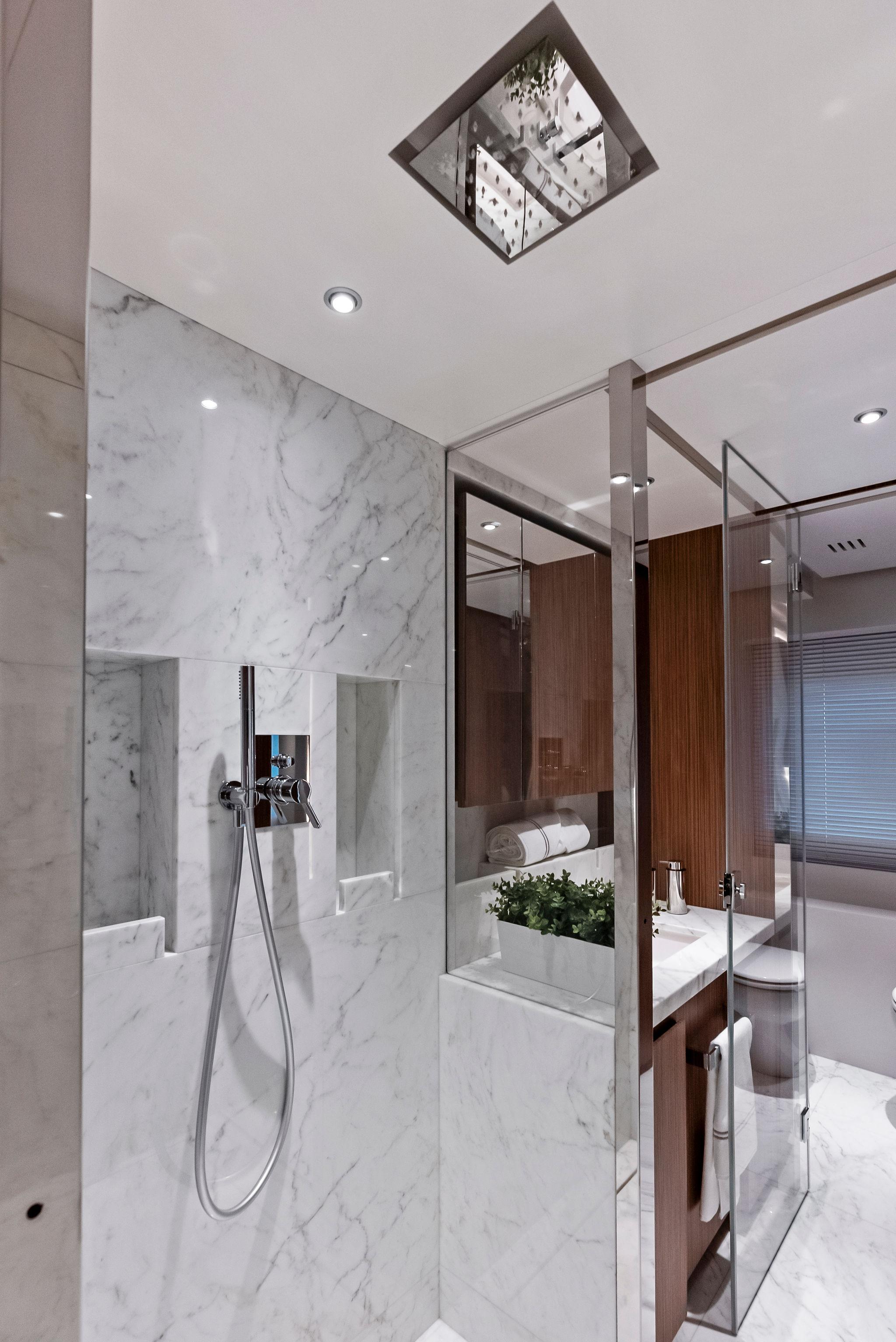
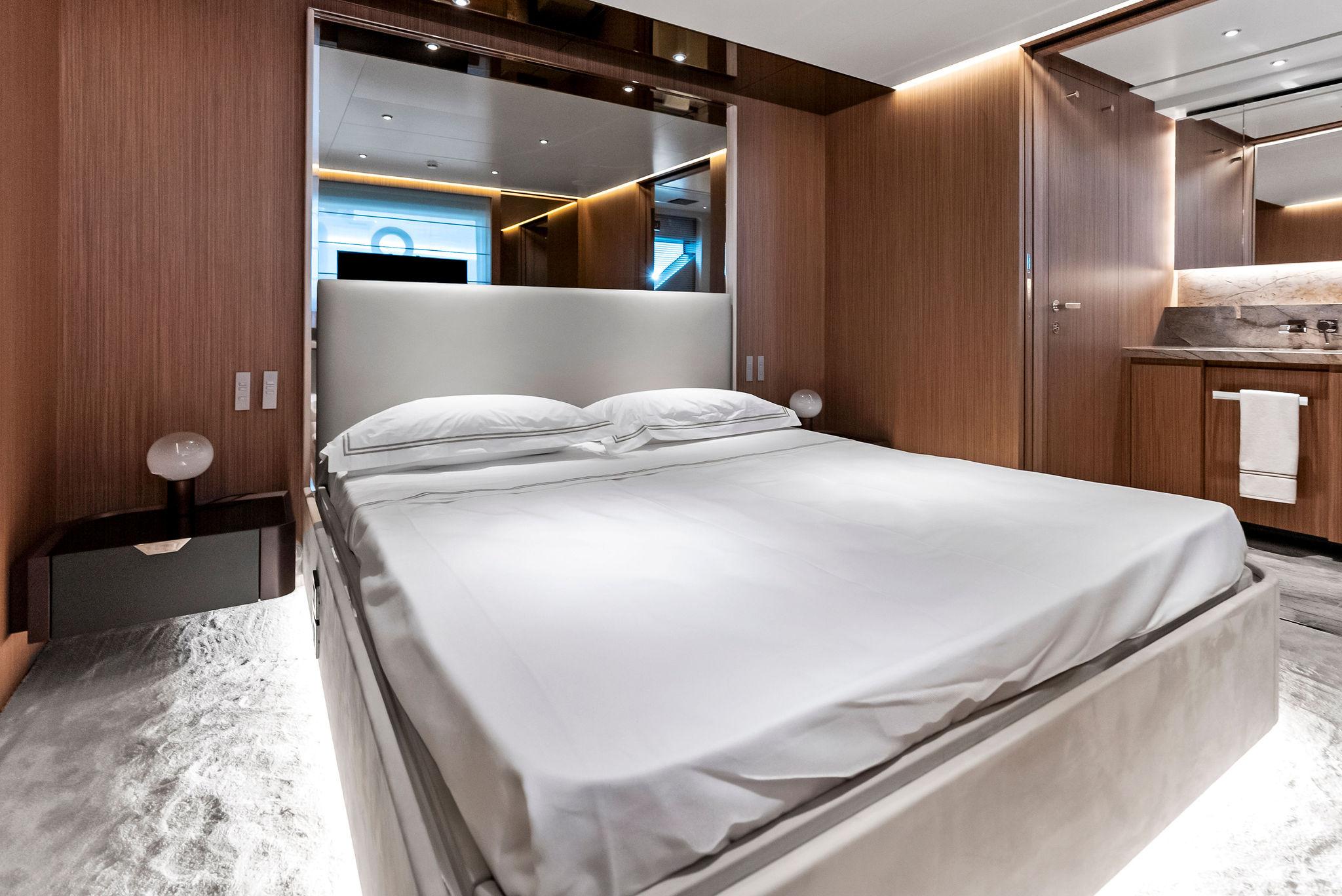
Interior
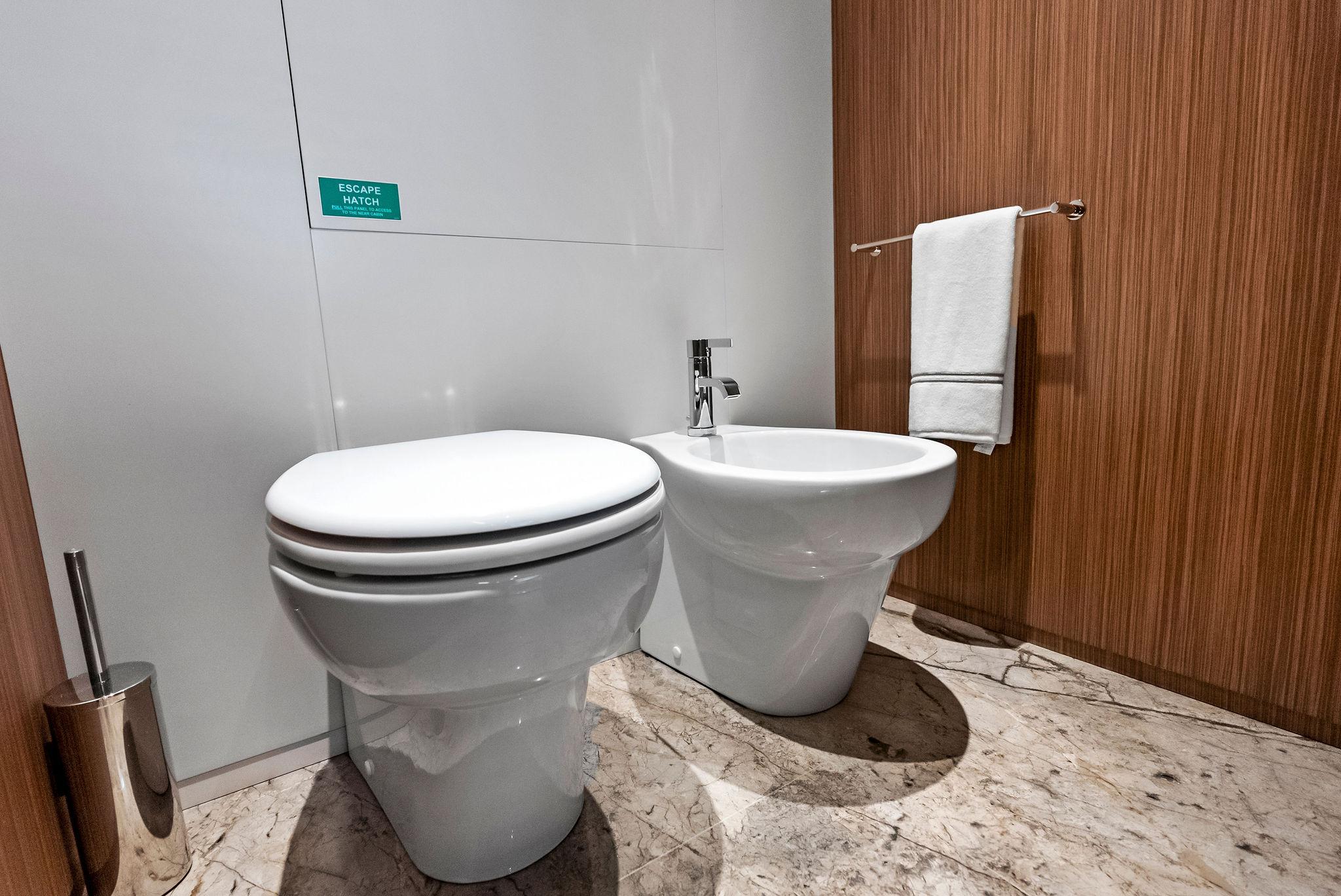
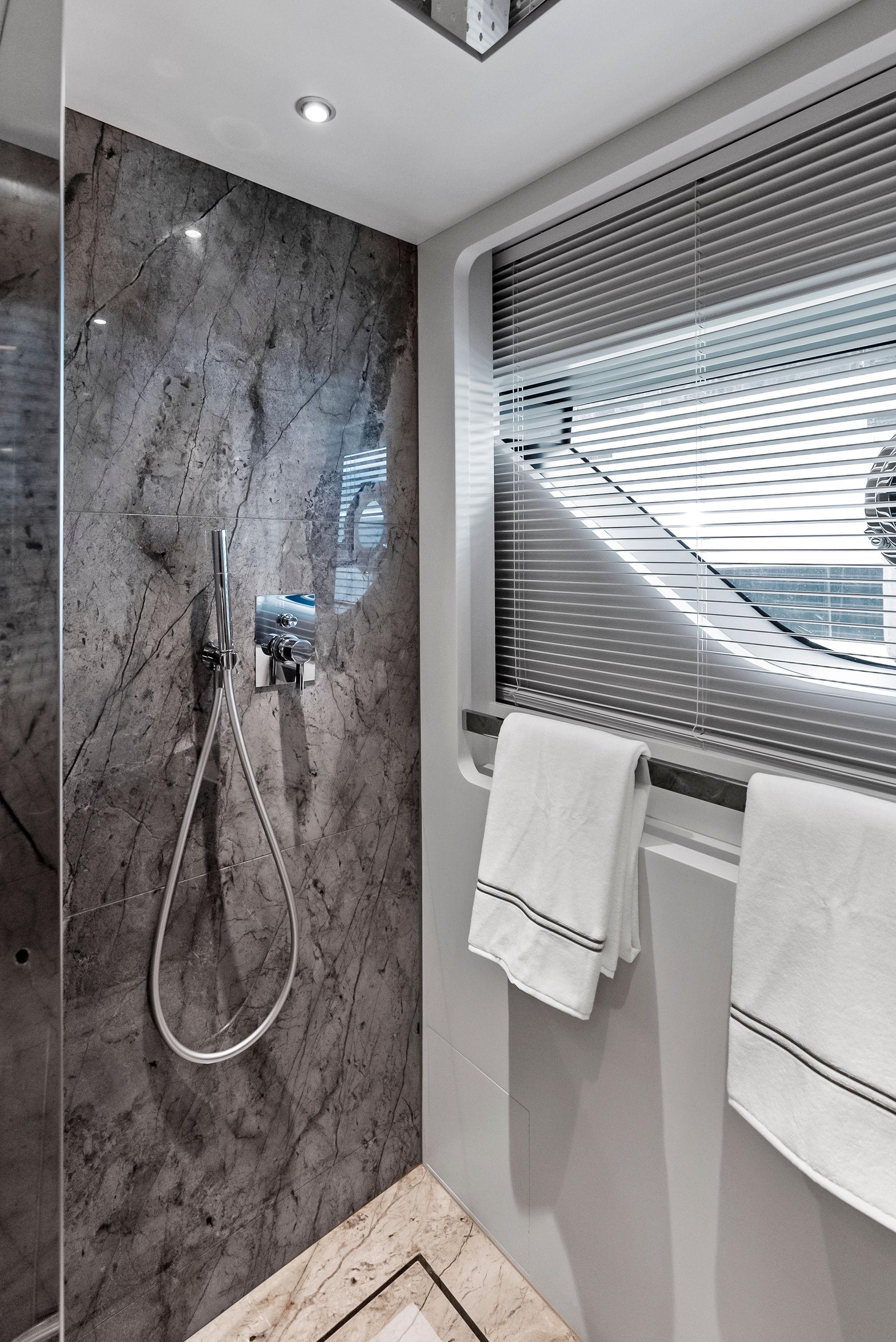
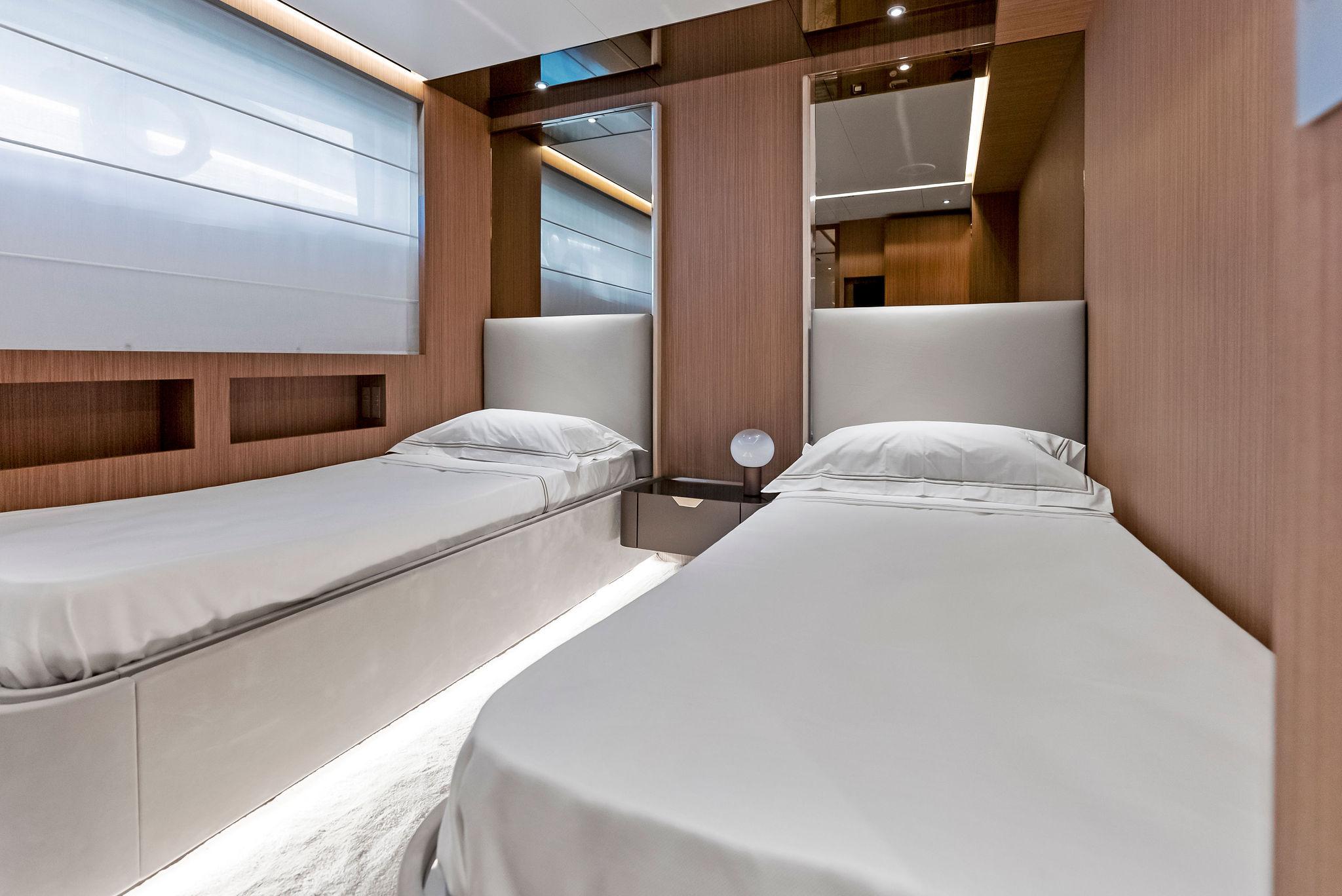
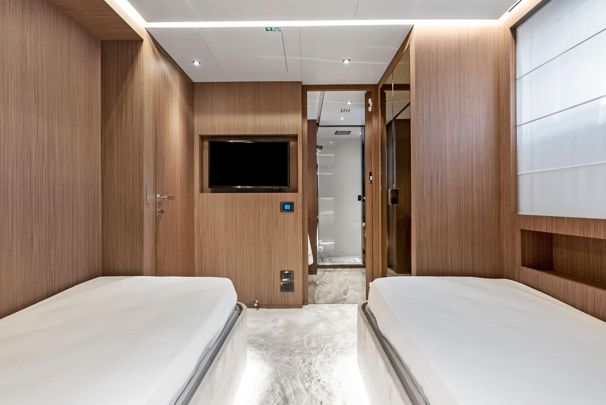
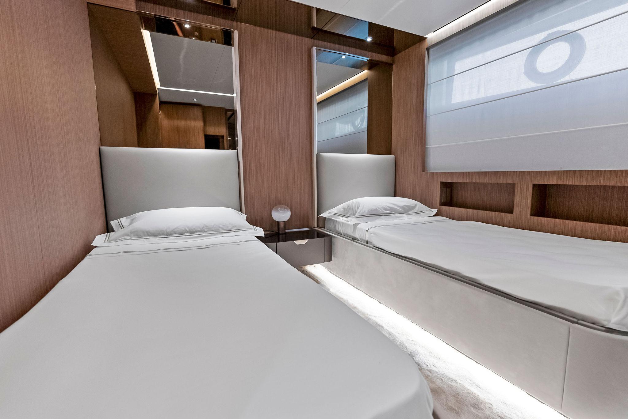
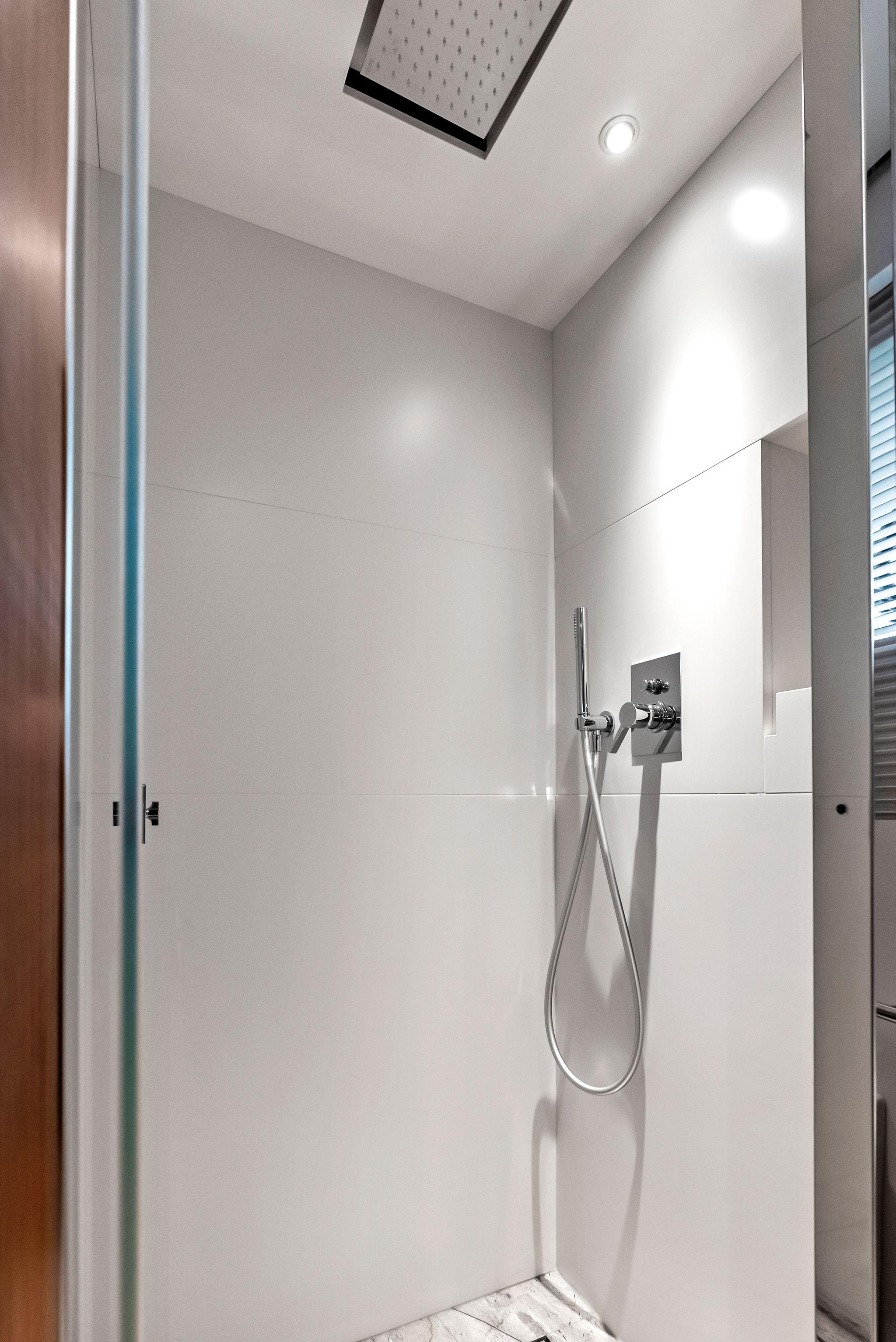
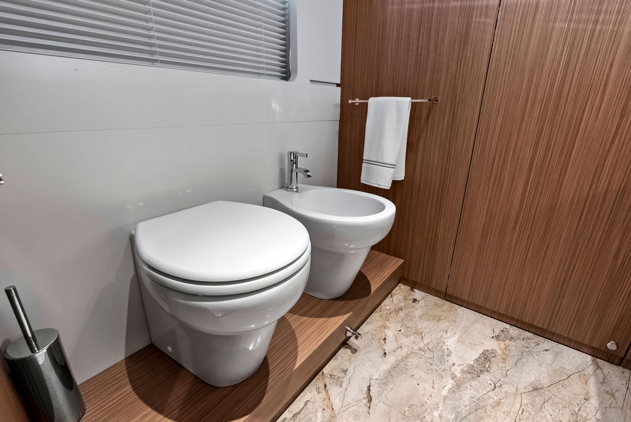
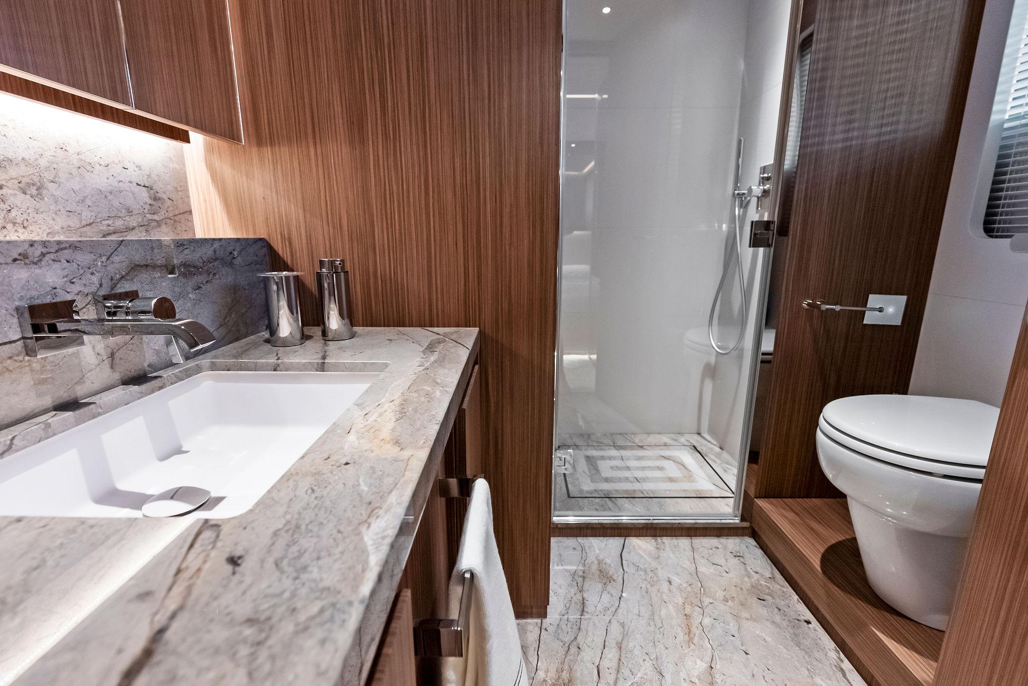
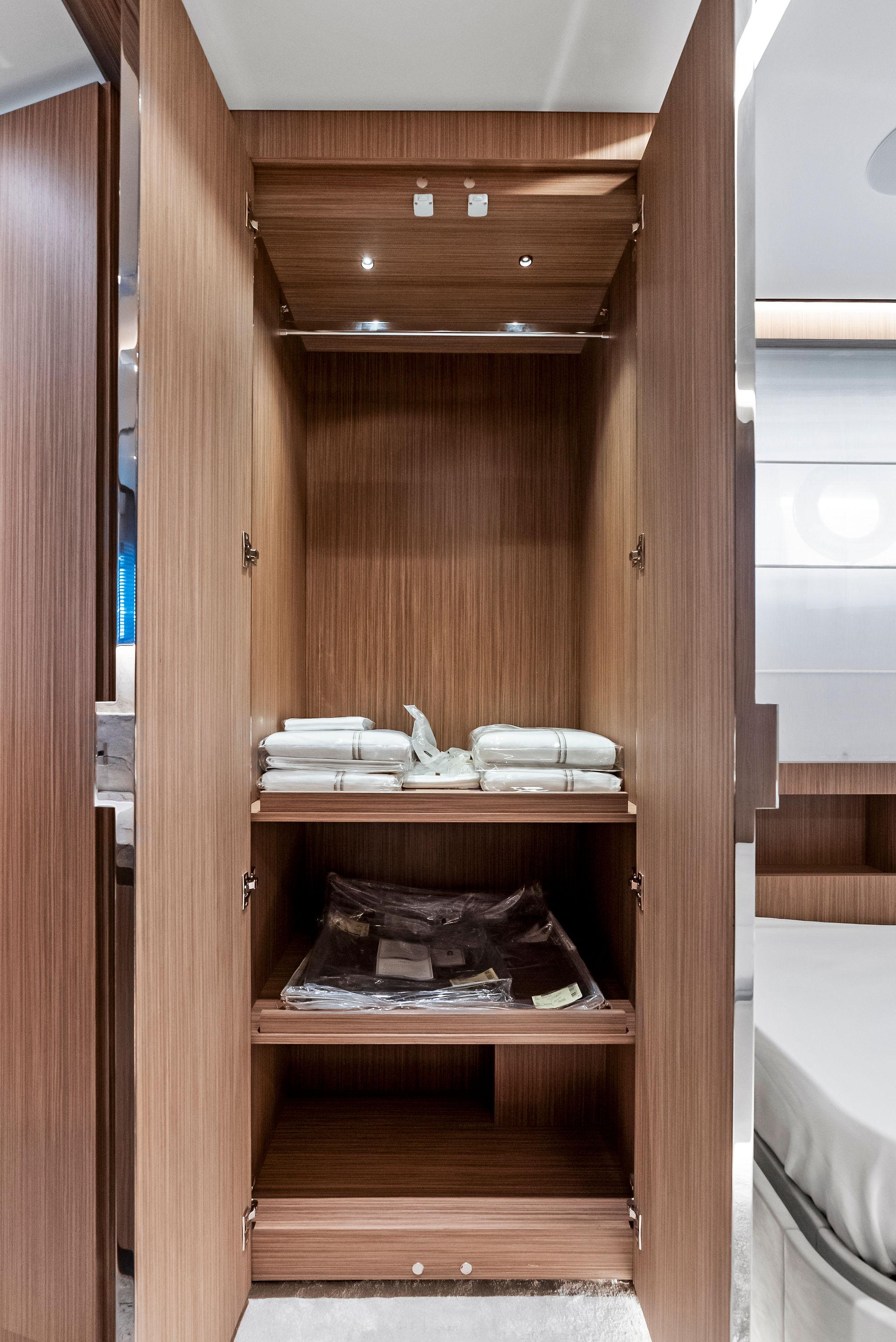
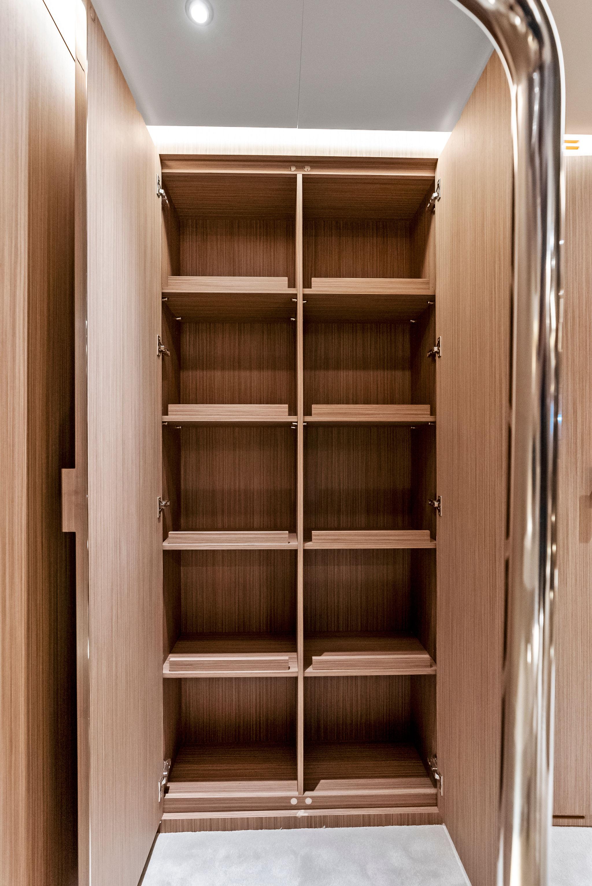
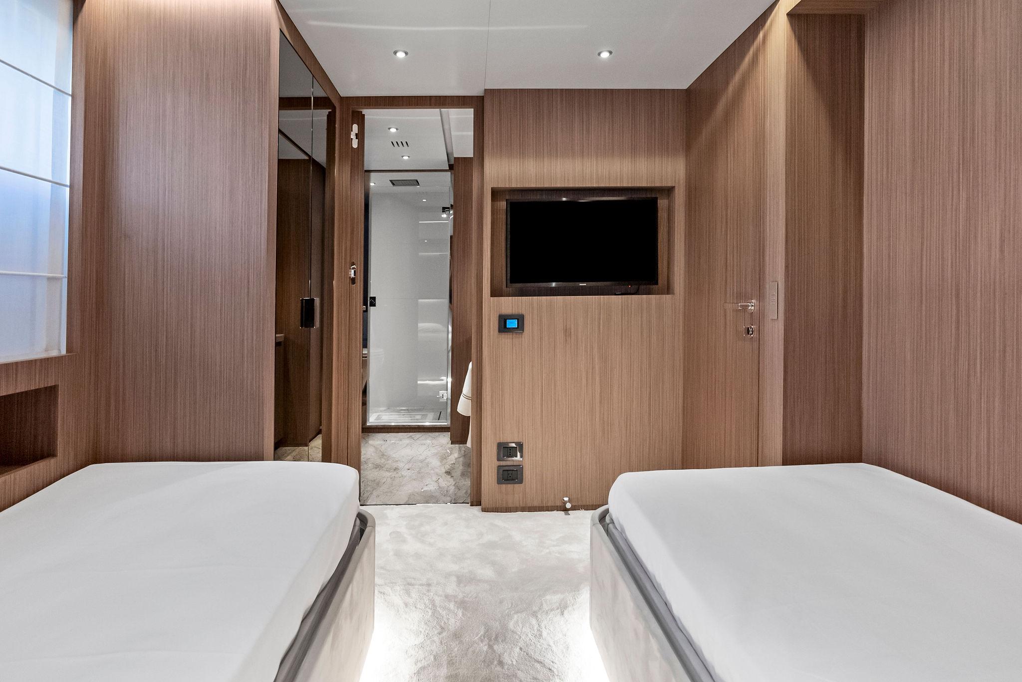
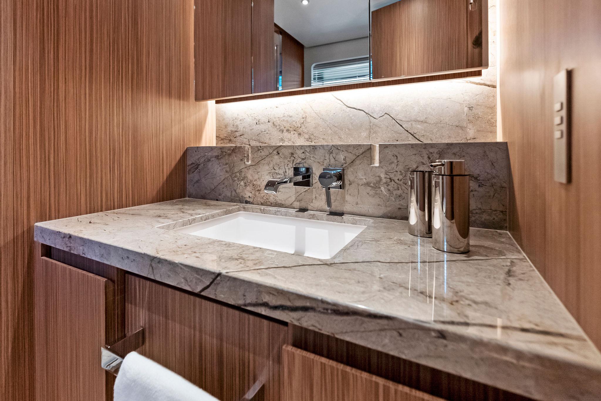
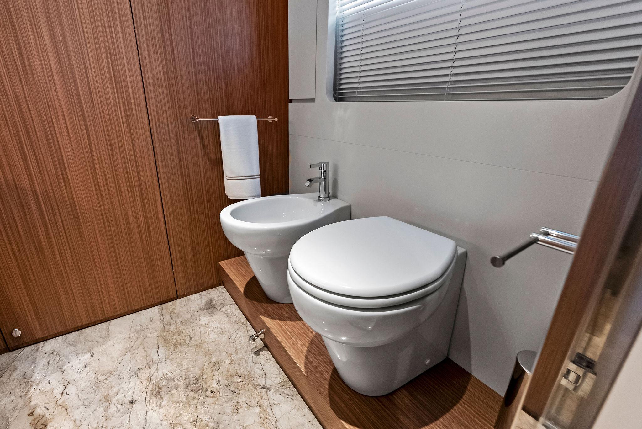
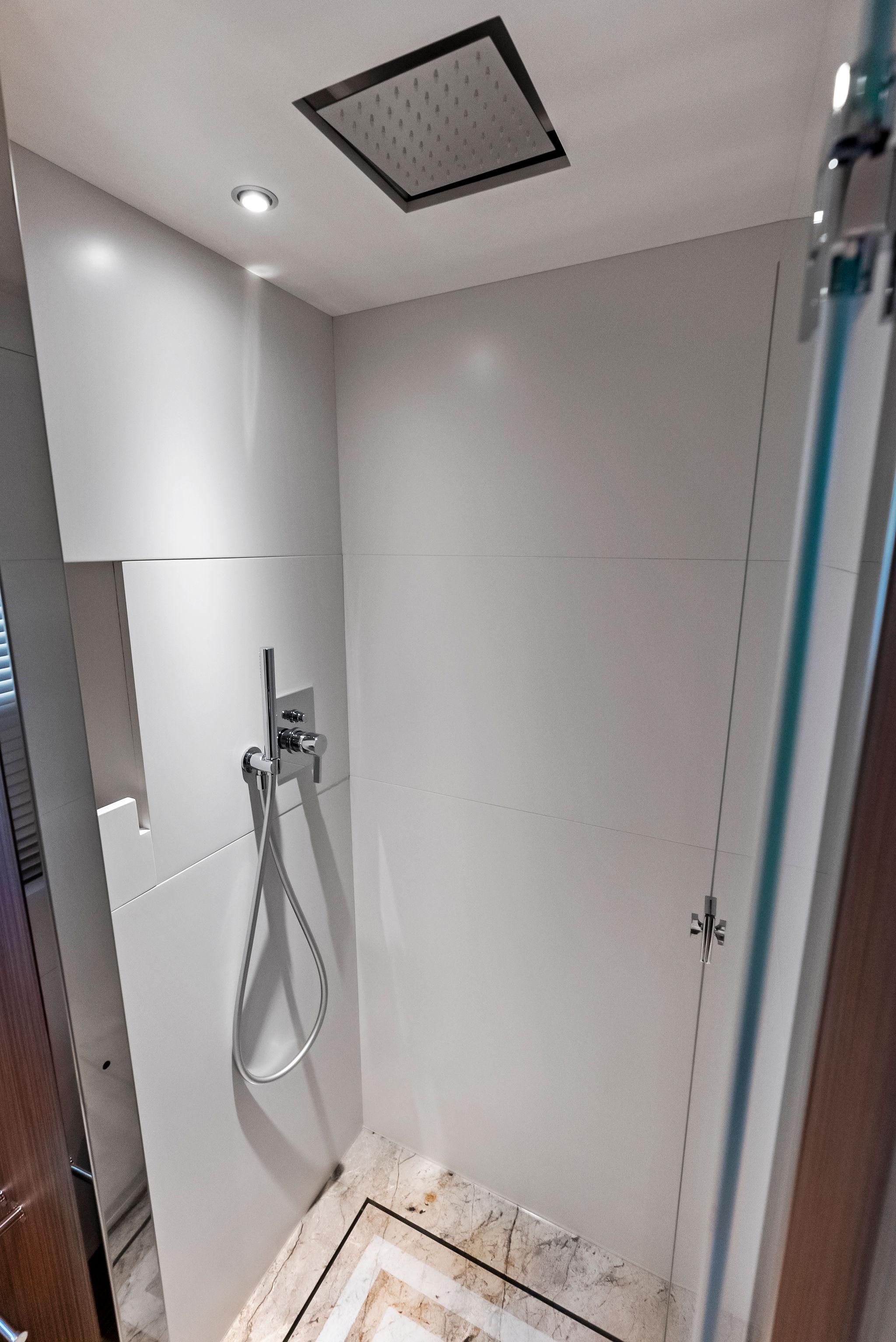
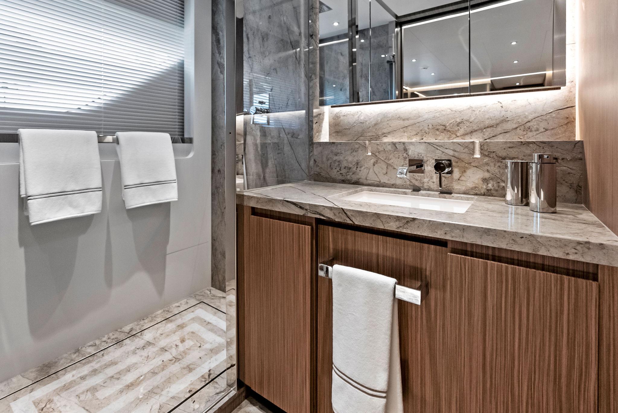
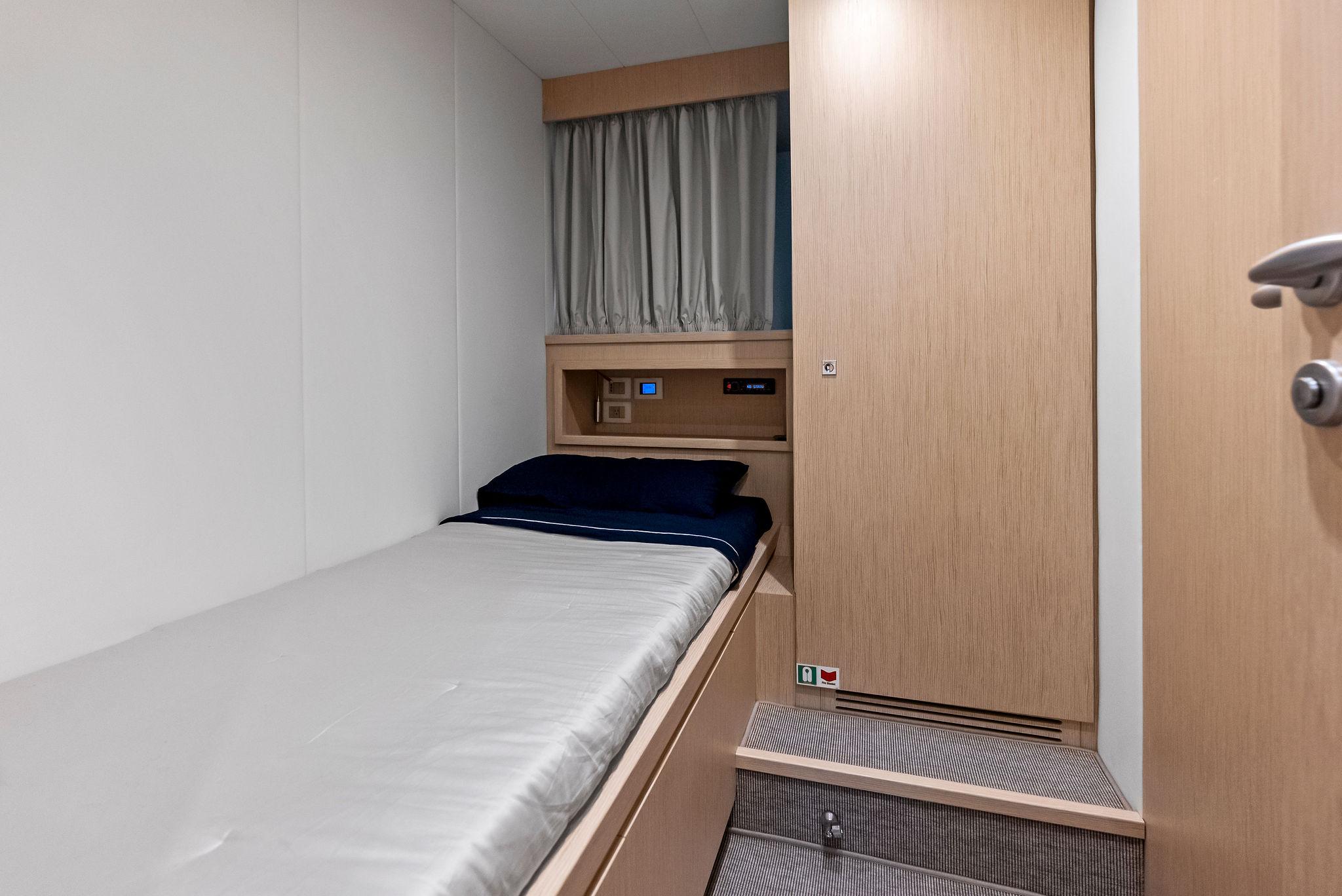
LOWER DECK AND GUEST AREA
MAIN DECK
UPPER DECK
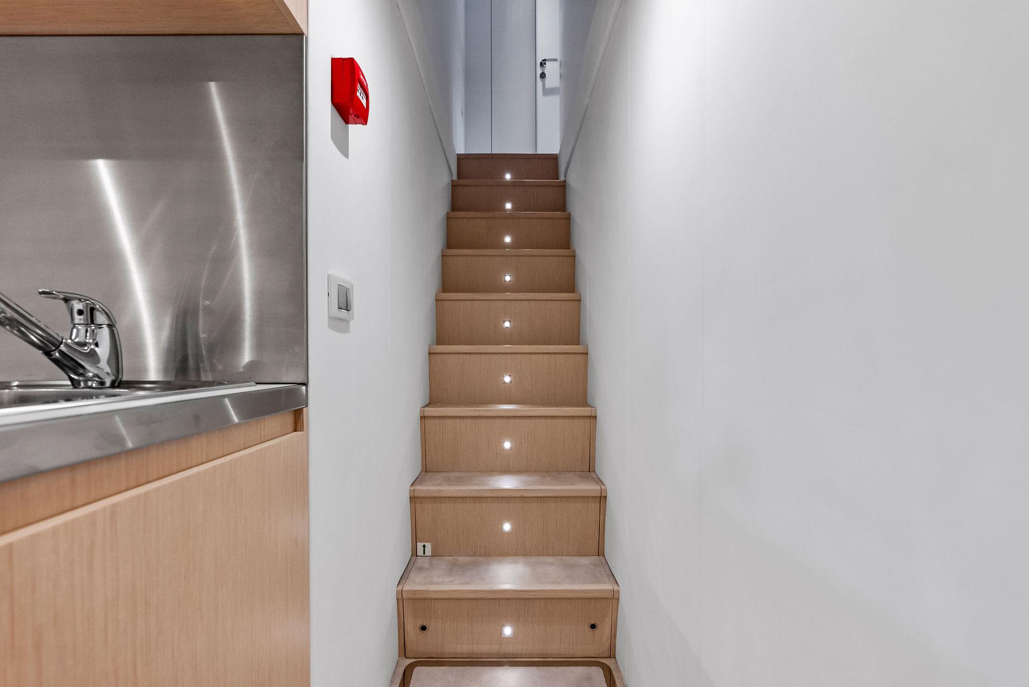
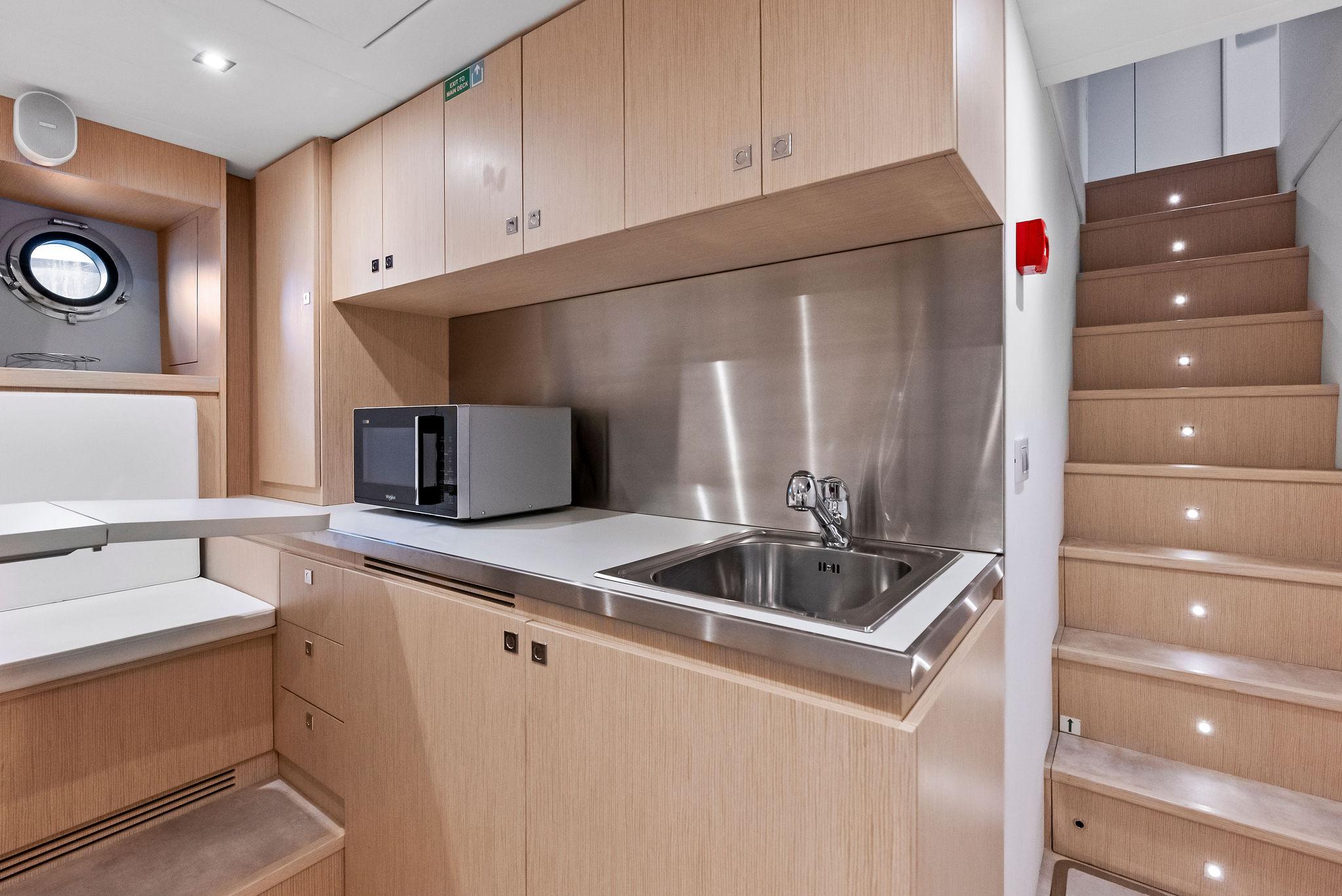
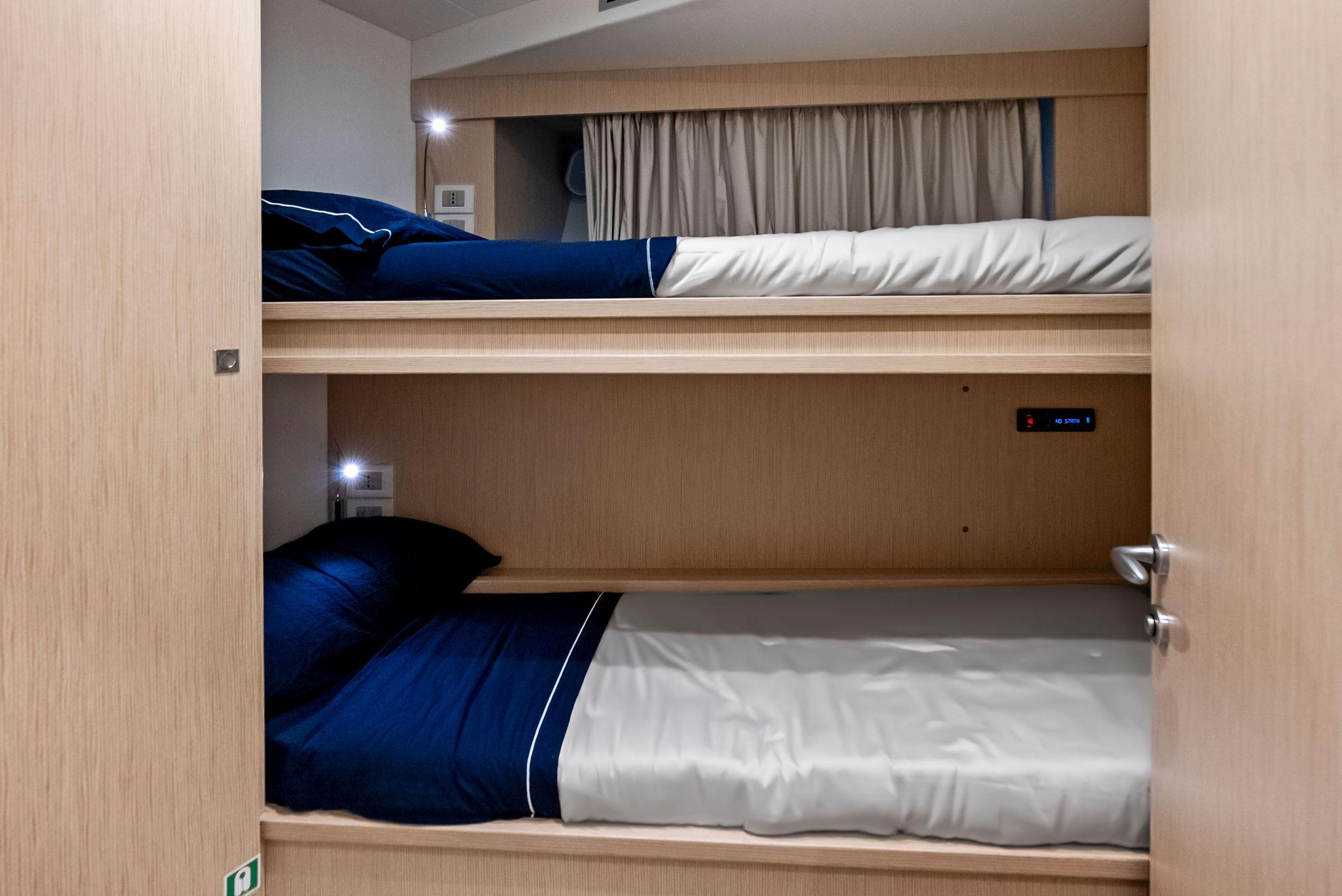
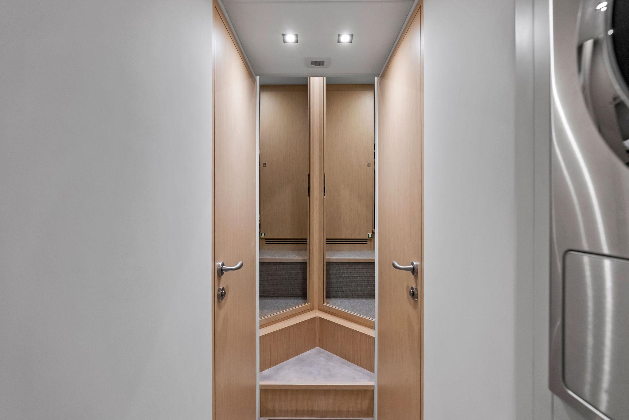
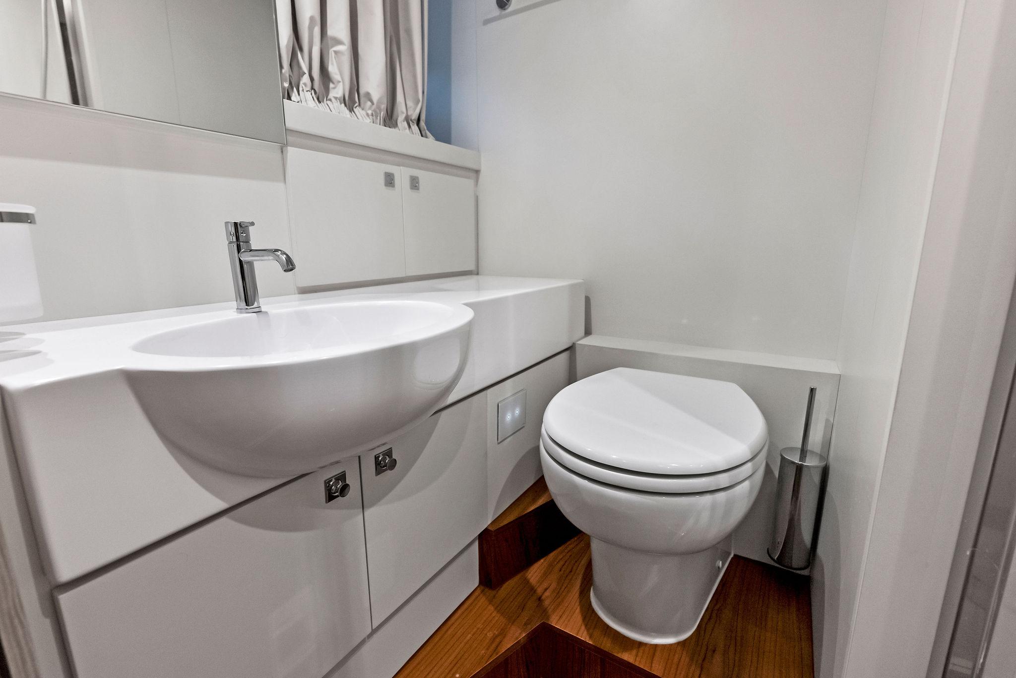
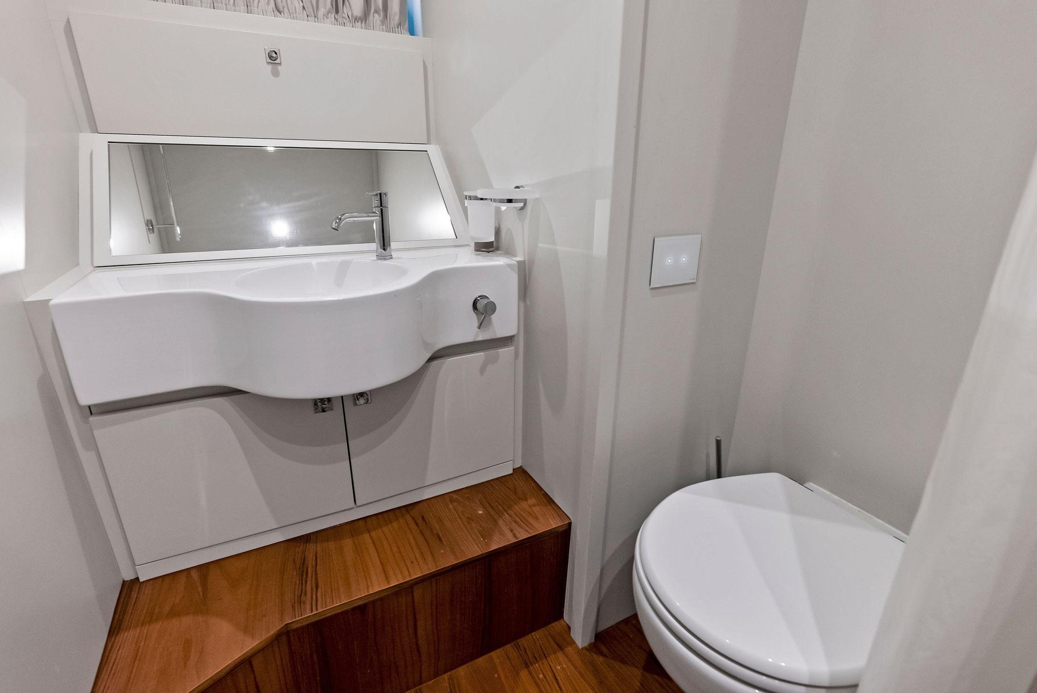
CREW AREA (5 CREW)
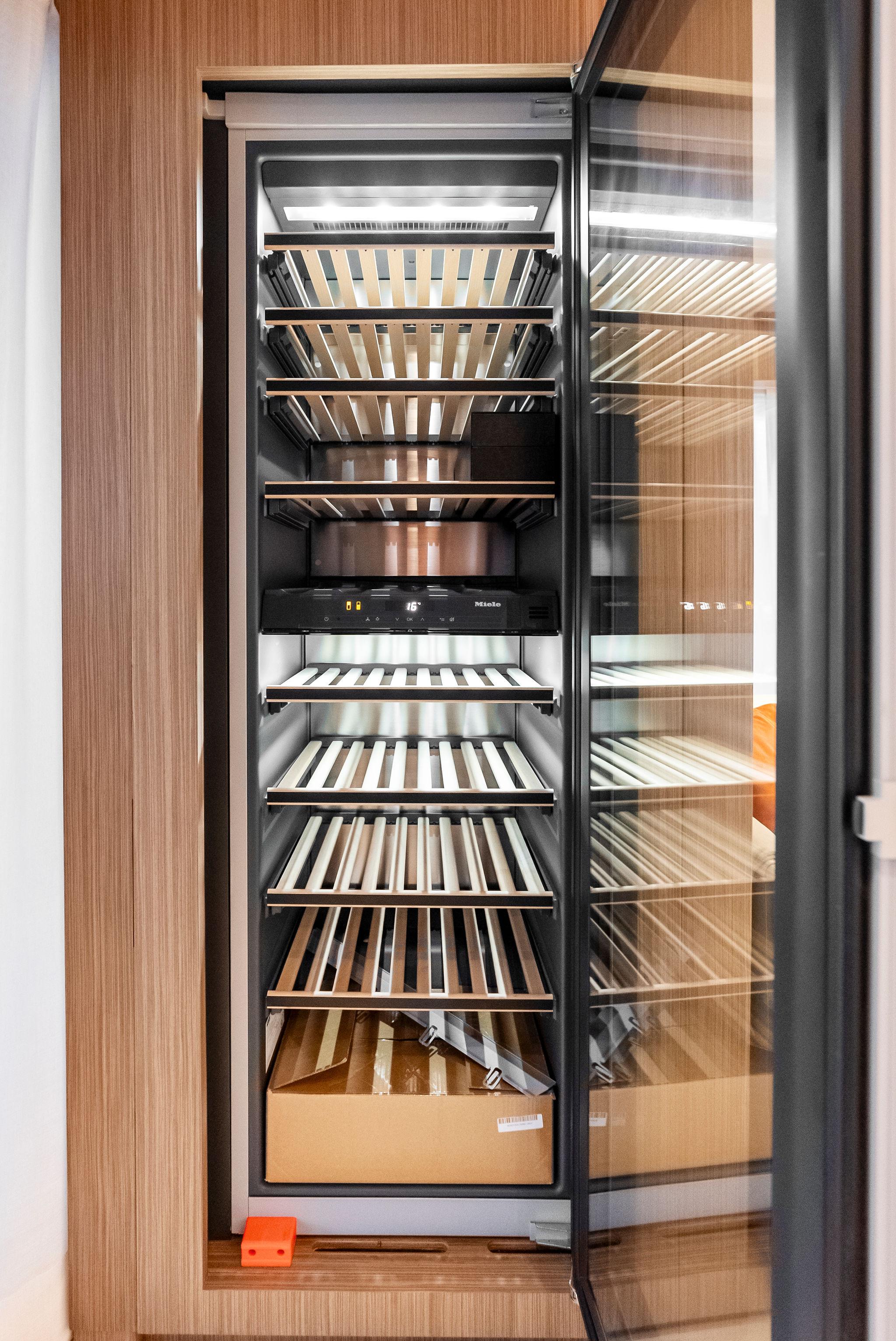
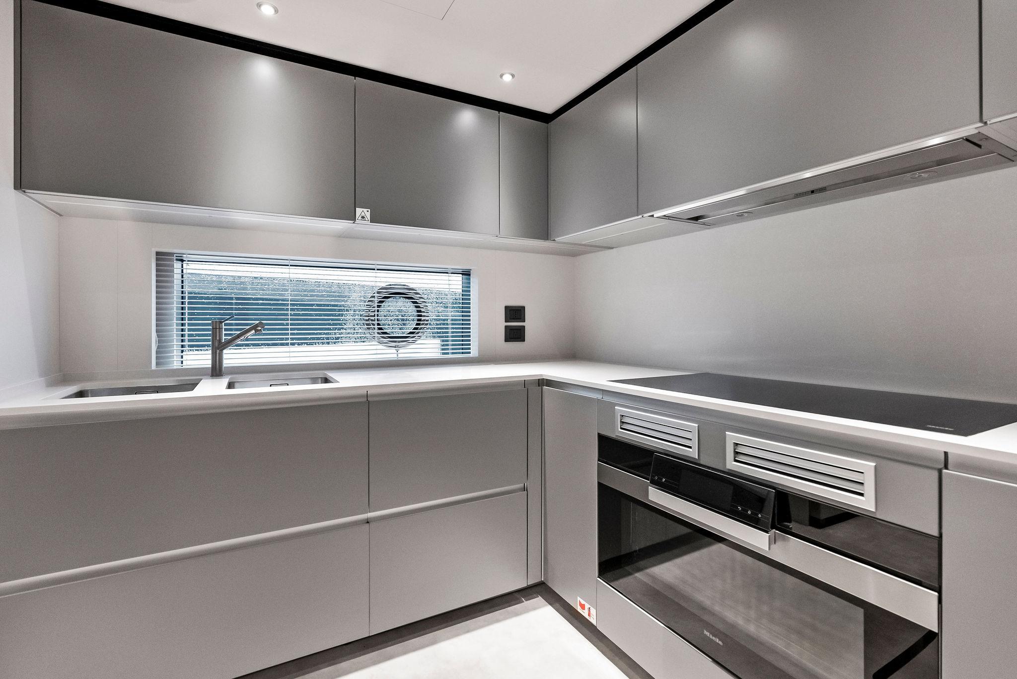
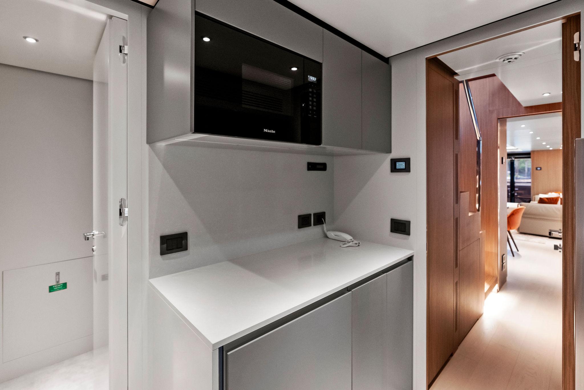
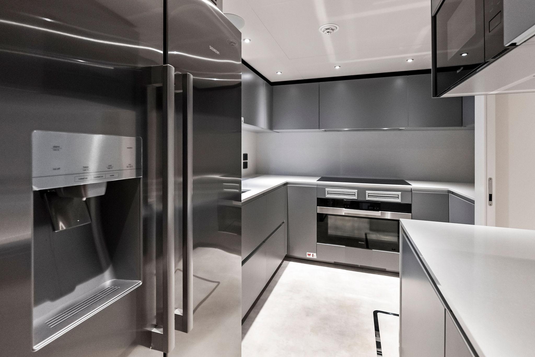
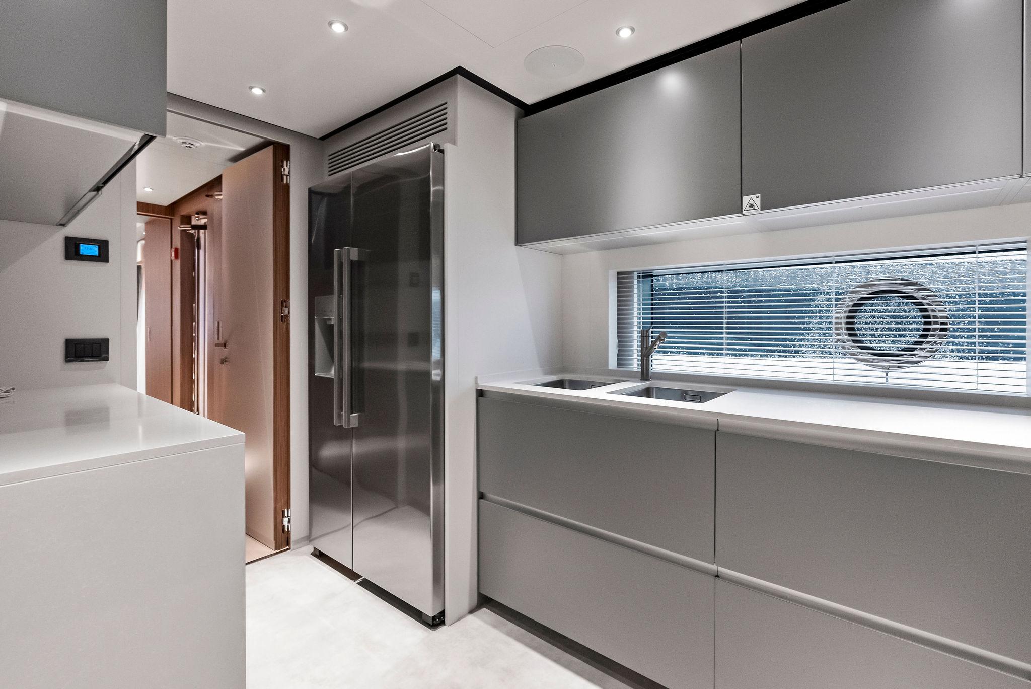
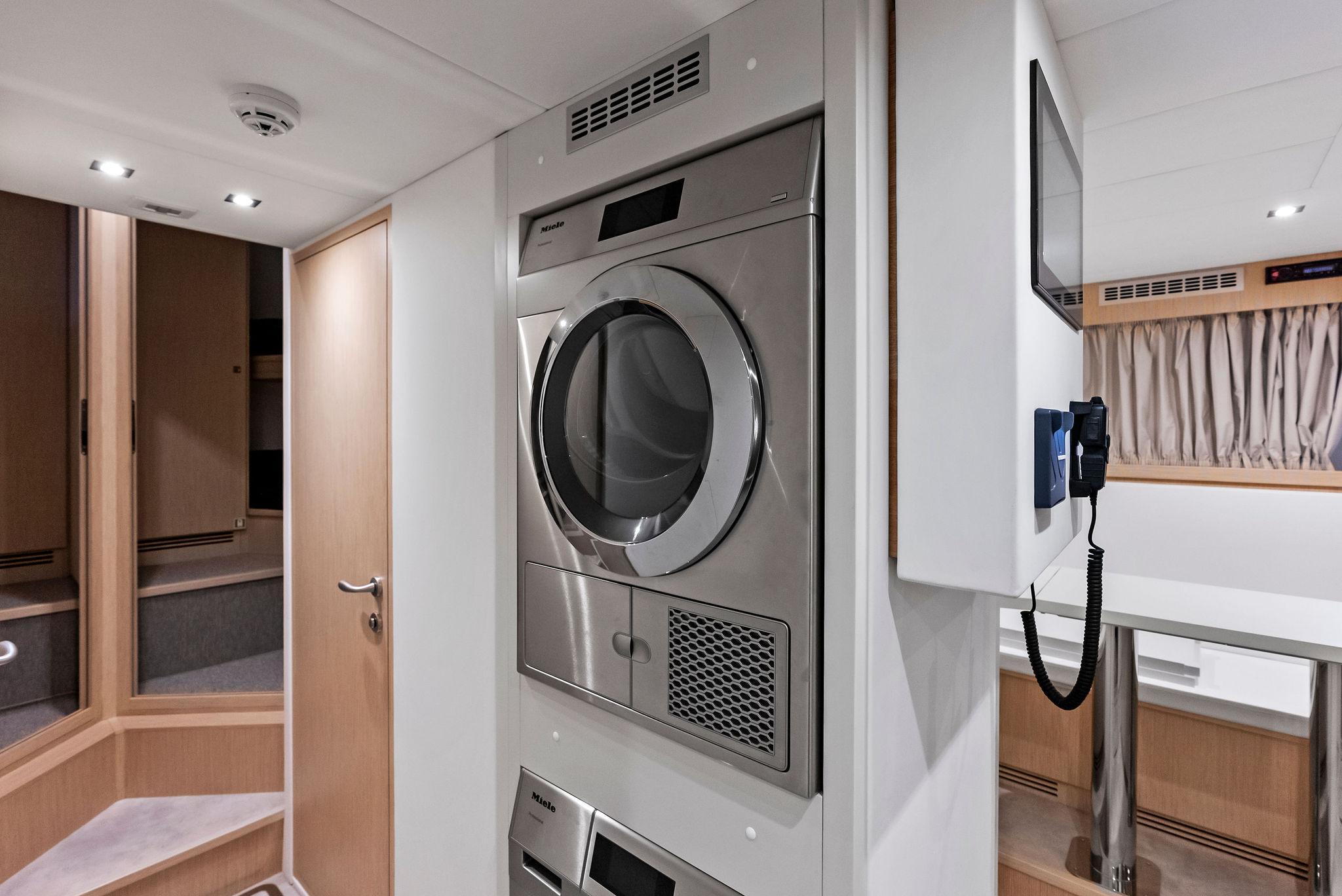
APPLIANCES
Galley:
Pantry Main Deck:
Crew mess:
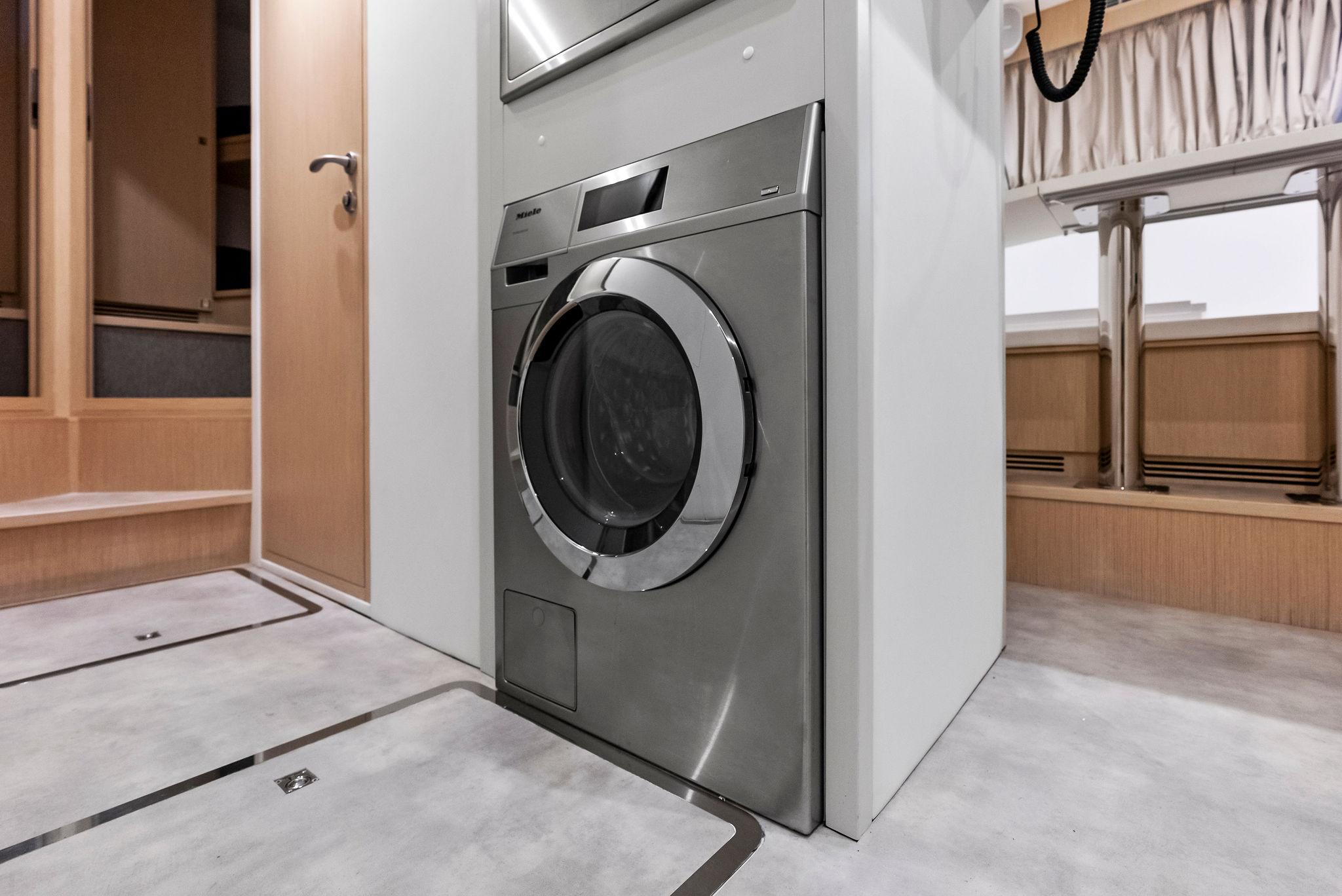
Laundry (crew area):
Sun Deck:
Disclaimer
The Company offers the details of this vessel in good faith but cannot guarantee or warrant the accuracy of this information nor warrant the condition of the vessel. A buyer should instruct his agents, or his surveyors, to investigate such details as the buyer desires validated. This vessel is offered subject to prior sale, price change, or withdrawal without notice.